
Automatic low resistance test device

A test device and low-resistance technology, which is applied in the direction of measuring device, measuring resistance/reactance/impedance, measuring electrical variables, etc. problems, to achieve the effect of improving test reliability, high test efficiency and easy reading

Inactive Publication Date: 2015-12-16
XIANGTAN UNIV
View PDF7 Cites 10 Cited by
  • Summary
  • Abstract
  • Description
  • Claims
  • Application Information

AI Technical Summary

Problems solved by technology

[0004] (1) The test method is manual point-to-point test, which has low test efficiency and high labor costs;
[0005] (2) The test item is the circuit resistance of the circuit of the pyrotechnic product that is selected. During the test, it is necessary to ensure that the lead wires of the corresponding test items are in correct contact with the tester's tester. When there are too many leads, manual measurement is very easy to mistest and miss;
[0006] (3) Practice shows that the resistance value of some test items of pyrotechnic products is less than 0.5Ω, and the resistance test results of the above equipment include the line resistance of the equipment itself, resulting in inaccurate resistance test
[0007] A multi-channel measurement method is also disclosed in the prior art to improve test efficiency. The test plan is to use multiple channels to perform multiple resistance measurements at the same time. According to this plan, during the test process, the explosive device to be tested will have multiple The gated loop is easy to cause safety hazards, and the correct test results cannot be obtained

Method used


Image

  • Automatic low resistance test device
  • Automatic low resistance test device
  • Automatic low resistance test device

Examples


Embodiment Construction

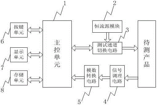
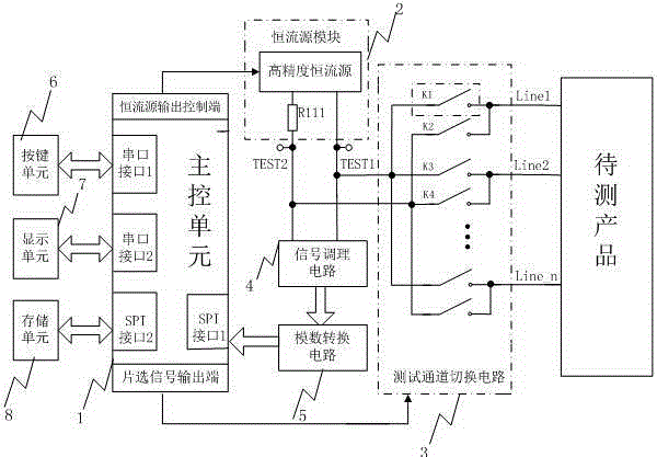
[0036] The preferred embodiments of the present invention will be further described below in conjunction with the accompanying drawings. An automatic low resistance test device such as figure 1 with 2 As shown, it includes a main control unit 1 , a constant current source module 2 , a test channel switching circuit 3 , a signal conditioning circuit 4 , an analog-to-digital conversion circuit 5 , a key unit 6 , a display unit 7 and a storage unit 8 .

[0037] The test channel switching circuit 3 is composed of a CPLD and a switch module, and each lead wire of the product is respectively connected to the positive test point TEST1 and the negative test point TEST2 through two switch modules. The switch module structure is as image 3 As shown, the module includes a transistor Q1, a resistor R101, a resistor R102 and a normally open relay FR. When the corresponding driving signal CPLD_S1 is at high level, the transistor Q1 is turned on, and the relay is closed due to the curren...


PUM


Abstract

The invention relates to an automatic low resistance test device and belongs to the resistance testing technical field. The automatic low resistance test device is especially suitable for initiating explosive device resistance tests. The automatic low resistance test device includes a main control unit 1, a constant current source module 2, a test channel switching circuit 3, a signal conditioning circuit 4, an analog-to-digital conversion circuit 5 and the like; the main control unit 1 successively outputs chip selection codes of a positive test channel and a negative test channel according to corresponding test items so as to control the test channel switching circuit 3 to perform switching, so that the output current of the constant current source module 2 can pass through a gated initiating explosive device loop; the signal conditioning circuit 4 performs filtering and differential amplification on port voltage of the gated loop; the analog-to-digital conversion circuit 5 acquires related voltage signals and transmits the voltage signals to the main control unit 1 for calculation, so that the resistance values of a tested item under test current of different directions can be obtained, and the test result of the tested item can be obtained through averaging; and the main control unit 1 repeats the above steps according to a preset test sequence so that test on the other test items can be completed; and therefore, automatic, rapid and comprehensive test on the resistance of an initiating explosive device can be realized.

Description

technical field [0001] The invention belongs to the technical field of resistance testing, and relates to an automatic low-resistance testing device, which is especially suitable for testing the resistance of pyrotechnics. Background technique [0002] In the prior art, when it comes to resistance measurement, a commercially available resistance tester or multimeter is generally used. However, when measuring the resistance of pyrotechnics, for safety reasons, the test current must be strictly limited to a small value range (below 5mA). When the test current is very small, the voltage generated at both ends of the measured resistance is also very small, so if the directional interference potential such as thermoelectric potential generated between dissimilar metals and primary battery potential will seriously affect the test results, it is obvious that ordinary test equipment does not The above problems cannot be solved. Therefore, some special test devices have appeared, s...

Claims


Application Information

Patent Timeline
Patent Type & Authority Applications(China)
IPC IPC(8): G01R27/14
Inventor 肖业伟谢润帮柯兴利张奇峰杨昭阳敏王正强
Owner XIANGTAN UNIV
Learn More