
Reflective digital holographic microscopic imaging device based on telecentric optical structure

A digital holographic microscopy and optical structure technology, applied in the direction of instruments, etc., can solve the problems of difficult position determination and adjustment, high system stability requirements, and phase distortion can not be completely eliminated, to improve accuracy, reduce complexity, Avoid the effects of aberrations and distortion

Inactive Publication Date: 2015-12-16
NANJING UNIV OF SCI & TECH
View PDF8 Cites 4 Cited by
  • Summary
  • Abstract
  • Description
  • Claims
  • Application Information

AI Technical Summary

Problems solved by technology

However, the two-step exposure method needs to record two holograms, which requires high system stability
The M.K.Kim research group in the United States proposed a method of physical compensation ([4] M.K.Kim. "Applications of Digital Holography in Biomedical Microscopy". J.Opt.Soc.Korea.2010, 14(2): 77-89), this method does not Instead of using a tube lens in the light path, another identical microscope objective lens was added to the reference light path in an attempt to make the curvature of the spherical reference light the same as that of the spherical object light, thereby eliminating the secondary phase distortion in the experimental recording, However, the position of the second microscope objective lens added by this method is difficult to determine and adjust, and a slight position shift will cause phase distortion that cannot be completely eliminated

Method used


Image

  • Reflective digital holographic microscopic imaging device based on telecentric optical structure
  • Reflective digital holographic microscopic imaging device based on telecentric optical structure
  • Reflective digital holographic microscopic imaging device based on telecentric optical structure

Examples


Embodiment Construction

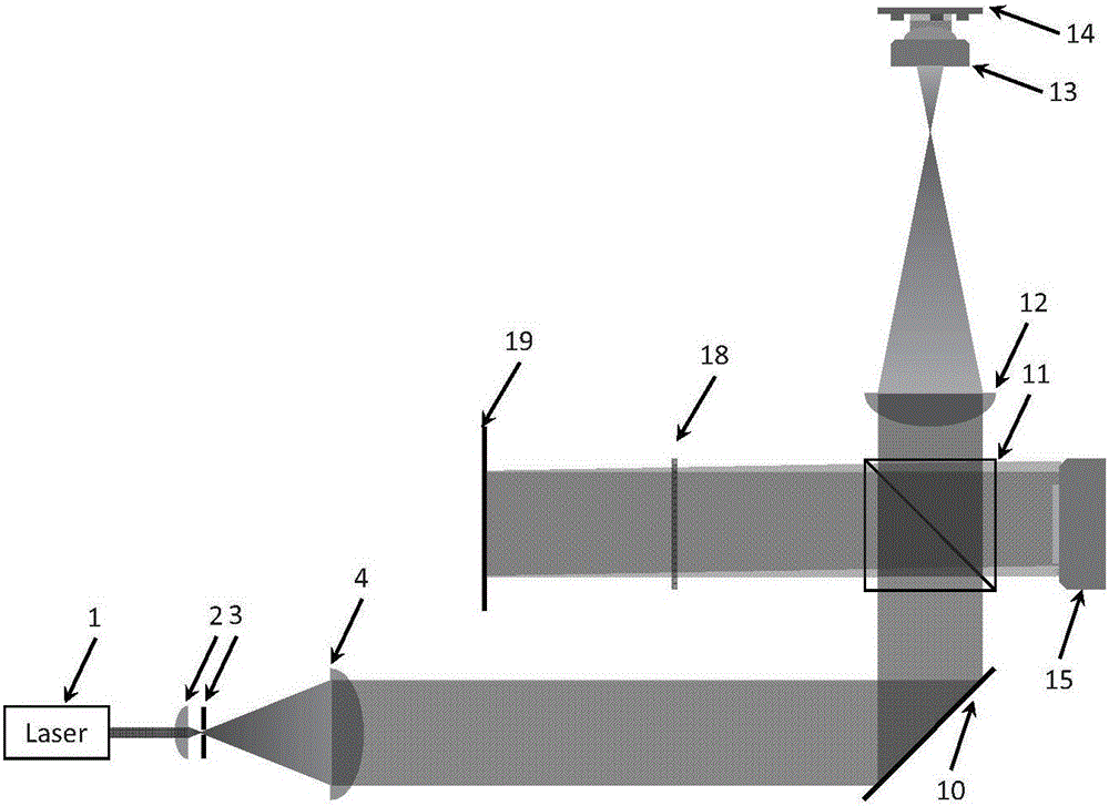
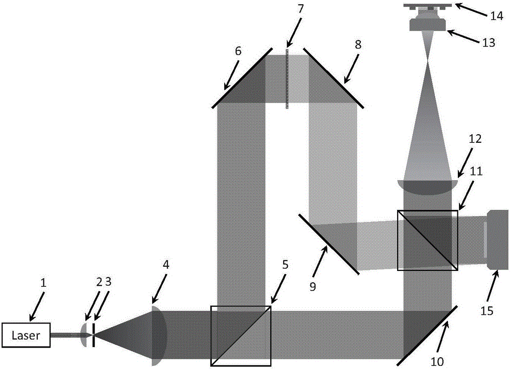
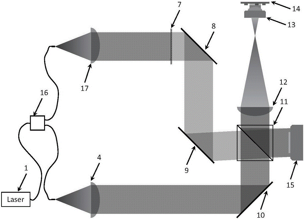
[0010] As shown in Figure 1 (a), the reflective digital holographic microscopic imaging device based on the telecentric optical structure of the present invention includes a laser 1, a collecting mirror 2, a pinhole diaphragm 3 of the collecting mirror, a first collecting mirror 4, and a first plane mirror 10. The second beam splitter 11, the lens tube lens 12, the microscope objective lens 13, the camera 15, the first attenuation sheet 18 and the second plane mirror 19, the pinhole diaphragm 3 of the condenser lens is placed behind the condenser lens 2 The position of the focal plane is also the position of the front focal plane of the first condenser lens 4; where the laser light emitted by the laser 1 is converged to the pinhole diaphragm 3 of the condenser mirror through the condenser mirror 2, and the light is diverged by the pinhole diaphragm 3 of the condenser mirror and then absorbed by the first The condenser lens 4 collects and becomes parallel light, and then is refl...


PUM


Abstract

The invention discloses a reflective digital holographic microscopic imaging device based on a telecentric optical structure. The reflective digital holographic microscopic imaging device adopts the telecentric optical structure, so that two parallel beams of object light and reference light interfere with each other to form an interferogram on an imaging plane of a camera, thereby avoiding aberration in the traditional digital holographic microscopic imaging device, greatly increasing system accuracy degree, and reducing complexity of later calculation and processing since other complicated physical or computing aberration compensation processes are not needed.

Description

technical field [0001] The invention belongs to optical measurement and imaging technology, in particular to a reflective digital holographic microscopic imaging device based on a telecentric optical structure. Background technique [0002] As a new type of coherent measurement and imaging technology, digital holography has the biggest advantage of being able to simultaneously and independently obtain quantitative amplitude information and phase information of objects. Phase information is particularly important when quantitatively detecting reflective objects with fine 3D optical structures. However, when using the traditional digital holographic microscope system for quantitative phase measurement, in order to obtain the phase image of the object accurately, the phase distortion in the reconstructed image must be corrected first, which requires knowing the various parameters in the experiment, such as Record the distance, the included angle of the object parameter, the ma...

Claims


Application Information

Patent Timeline
Patent Type & Authority Applications(China)
IPC IPC(8): G03H1/00G03H1/04
CPCG03H1/00G03H1/0443G03H2001/005
Inventor 陈钱孙佳嵩左超冯世杰顾国华张玉珍胡岩张良陶天阳李加基张佳琳孔富城林飞张敏亮范瑶
Owner NANJING UNIV OF SCI & TECH
Learn More