
Passive ultrahigh-frequency RFID tag for temperature alarming

A RFID tag and ultra-high frequency technology, applied in the field of passive ultra-high frequency RFID tags, can solve the problems of coil short circuit, high price of electronic tags, high cost of tags, etc., and achieve good impedance matching effect

Inactive Publication Date: 2015-12-16
南京三宝科技股份有限公司
View PDF4 Cites 2 Cited by
  • Summary
  • Abstract
  • Description
  • Claims
  • Application Information

AI Technical Summary

Problems solved by technology

Due to the low frequency, low-frequency electronic tags need to wind many thin coils on the iron core to make the tags resonate at the working frequency, which makes the cost of the tags higher; the working frequency of high-frequency electronic tags is increased, so that the tags resonate at the working frequency. The number of required label antenna coils is greatly reduced, and aluminum etching technology can be used to process the label. However, since the single-sided coil will cause a short circuit if the chip is welded, the double-sided aluminum etching technology can only be used, and the processing cost of the label is still relatively high. high
Due to its relatively high operating frequency, the UHF electronic label can be implemented with a single-sided antenna, and the cost is much lower than the first two electronic labels. However, compared with the traditional printed anti-counterfeiting, the price of the electronic label is still low. High, which greatly restricts the application of electronic tags

Method used


Image

  • Passive ultrahigh-frequency RFID tag for temperature alarming
  • Passive ultrahigh-frequency RFID tag for temperature alarming

Examples


Embodiment Construction

[0011] The present invention will be further explained below in conjunction with the accompanying drawings.

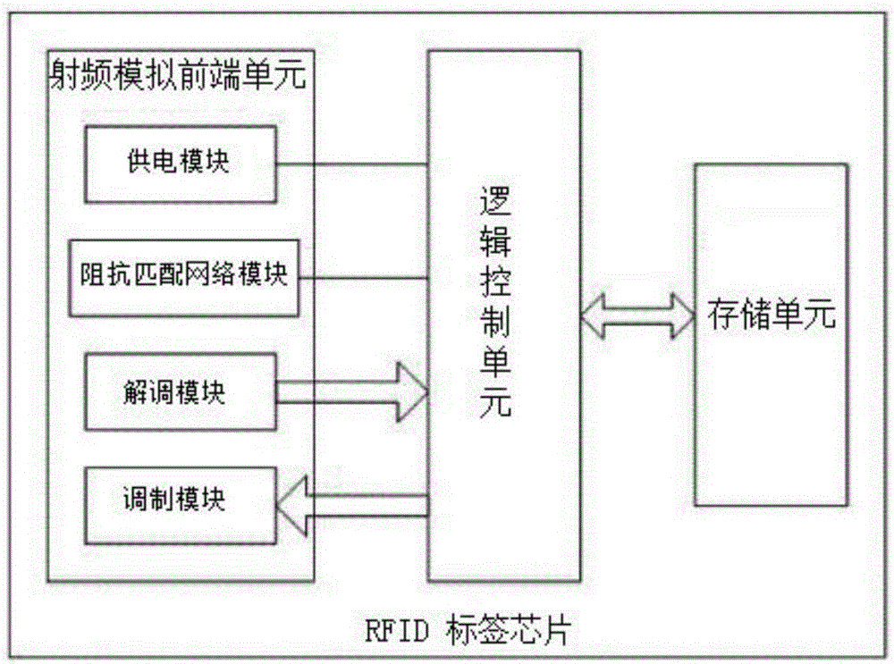
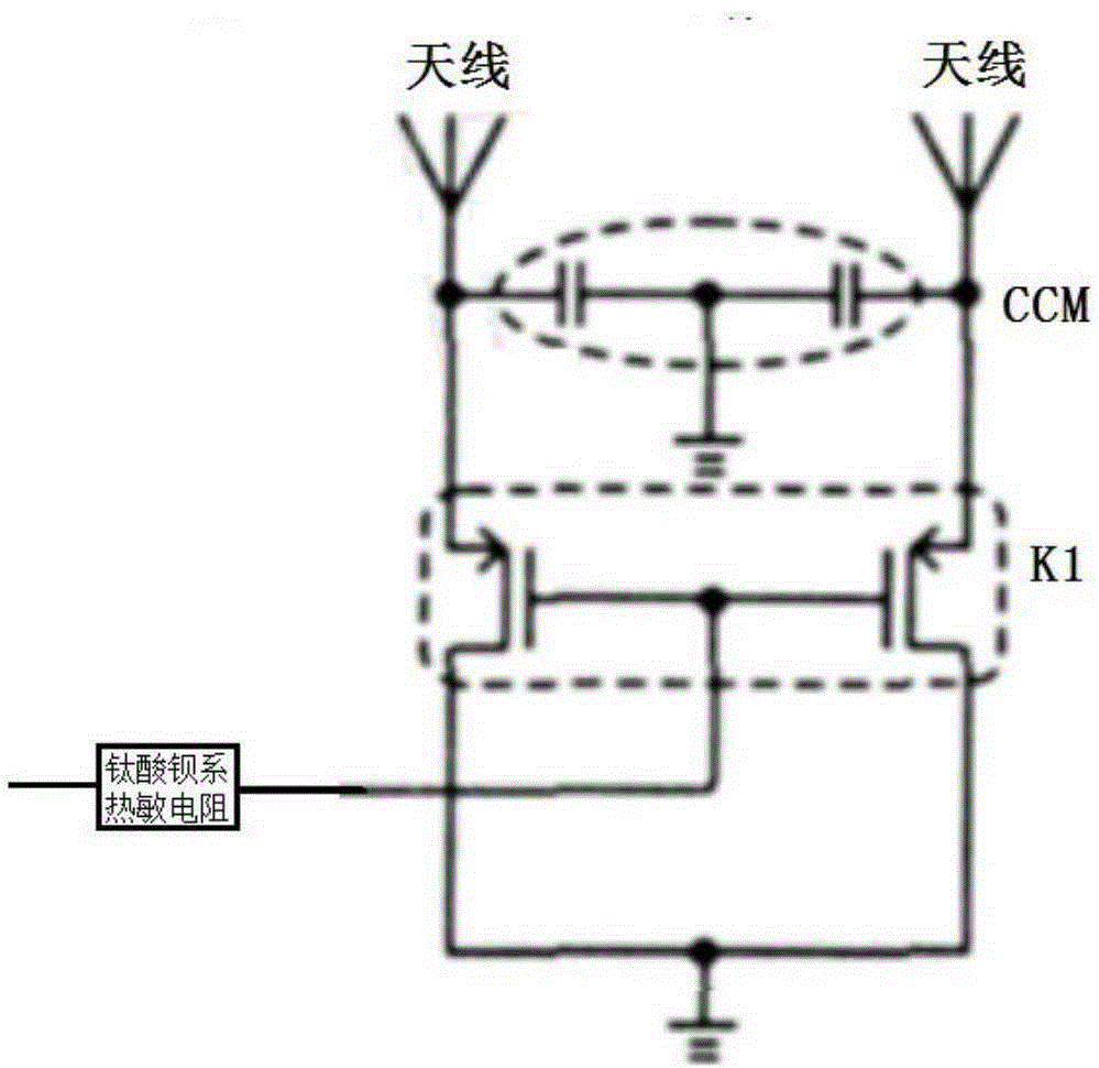
[0012] like figure 1 As shown, a passive ultra-high frequency RFID tag used for temperature alarm includes a tag chip and a tag antenna connected with the tag chip. The tag chip includes a radio frequency analog front-end unit, a logic control unit, and a storage unit that are connected in sequence. The RF analog front-end unit includes a power supply module, an impedance matching network module, a demodulation module and a modulation module respectively connected to the logic control unit. The impedance matching network module includes a first capacitor, a second capacitor, a first PMOS switch tube, a second PMOS switch tube, and a barium titanate thermistor. The first capacitor and the second capacitor are connected in parallel between the tag antenna and the ground; the gates of the first PMOS switch tube and the second PMOS switch tube are connected to the power ...


PUM


Abstract

The invention discloses a passive ultrahigh-frequency RFID tag for temperature alarming. The tag comprises a tag chip and a tag antenna connected with the tag chip, wherein the tag chip comprises a radio-frequency analog front-end unit, a logic control unit and a storage unit, which are connected in sequence. The radio-frequency analog front-end unit is connected with a power supply module, an impedance matching network module, a demodulation module and a modulation module of the logic control unit. The impedance matching network module comprises a first capacitor, a second capacitor, a first PMOS switch transistor, a second PMOS switch transistor and a barium titanate thermistor. The first capacitor and the second capacitor are connected in parallel between the tag antenna and the ground; and the gates of the first PMOS switch transistor and the second PMOS switch transistor are connected in series with the barium titanate thermistor and then are connected to the power supply module, the drains of the first PMOS switch transistor and the second PMOS switch transistor are connected to the signal feed-in end of the tag antenna, and the sources of the first PMOS switch transistor and the second PMOS switch transistor are grounded.

Description

technical field [0001] The invention relates to a passive ultra-high frequency RFID tag used for temperature alarm. Background technique [0002] The application of RFID (Radio Frequency Identification, radio frequency identification) technology is becoming more and more extensive. According to the needs of different application fields and actual environments, many specific requirements are also put forward for the radio frequency identification electronic tag itself. In anti-counterfeiting applications, labels are generally required to have requirements such as uniqueness, stability, safe use time, and difficulty in being imitated. The electronic label can have a globally unique code, and the unique code can not be changed. Using electronic tags for anti-counterfeiting has the characteristics of high difficulty in imitation, high imitation cost, and long imitation time. It is an excellent carrier for anti-counterfeiting applications. [0003] Currently commonly used RFID ...

Claims


Application Information

Patent Timeline
IPC IPC(8): G06K19/077
Inventor 辛柯俊吴涛吴剑李钢邹涛
Owner 南京三宝科技股份有限公司
Learn More