High-reliability remote control switching device

A switchgear, reliable technology, applied in the field of high-reliability remote switchgear, can solve the problems of complex overall structure, many components, heavy installation and debugging workload, etc.

Pending Publication Date: 2015-12-16
北京华美煜力电力技术有限公司
View PDF6 Cites 2 Cited by
  • Summary
  • Abstract
  • Description
  • Claims
  • Application Information

AI Technical Summary

Problems solved by technology

The disadvantages of these two methods are: the disadvantage of the first method is that although the optical cable system can avoid magnetism and eliminate the influence of electromagnetic induction and electrostatic induction, it cannot eliminate the electromagnetic induction and electrostatic induction in the long-distance power supply system, causing malfunction or failure of the electric operating mechanism. Refusal to move, the problem of misoperation and refusal of the electric operating mechanism under the control of the optical cable has already occurred in the high-speed rail catenary in operation
[0004] However, it has been found in actual use that the technical solution disclosed in Chinese patent 200910089763.7 also has certain shortcomings. First, because it uses a remote control signal transmitter and a remote control signal receiver located at both ends of the control cable, the device There are many components, the overall structure is relatively complicated, the installation and debugging workload is relatively large, and the cost is also high; secondly, because the electric operating mechanisms used in the existing high-voltage switches or isolating switches, they all use motors and relays or Formed by electrical components such as contactors, the forward or reverse rotation of the motor is controlled through relays or contactors. Even if the control cable can be reliably grounded when the remote control signal is not transmitted, the motor coil and the Relays or contactors are not grounded, they are still susceptible to external electromagnetic interference, in some serious cases, external electromagnetic interference will generate a high enough voltage in the relay or contactor to cause the motor to malfunction, resulting in serious security issues

Method used


Image

  • High-reliability remote control switching device
  • High-reliability remote control switching device

Examples


Embodiment Construction

[0018] The present invention will be specifically described below in conjunction with the accompanying drawings.

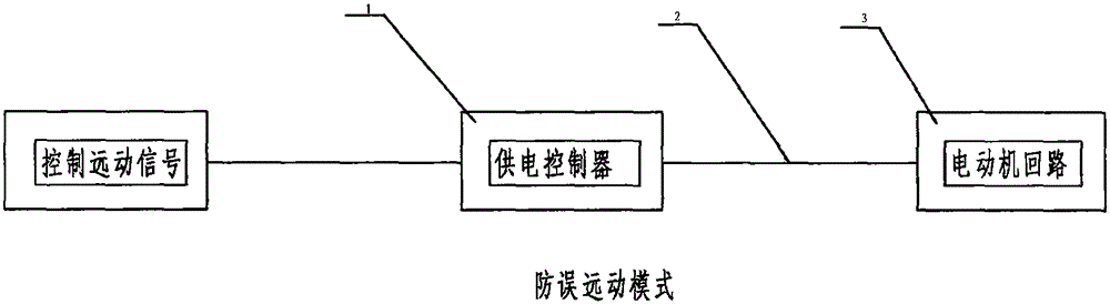
[0019] Such as figure 1 As shown, the high-reliability remote control switchgear of the present invention mainly includes three parts, namely a power supply controller 1, a control cable 2 and a motor circuit 3, wherein the power supply controller 1 can be arranged in the control room of a substation (substation), and the control cable One end of 2 is connected to the power supply controller 1, and the other end of the control cable 2 is directly connected to the motor circuit. When the power supply controller 1 receives the remote control signal, it supplies power to the motor circuit 3 in the electric operating mechanism through the control cable 2, and the motor will perform corresponding actions, such as forward rotation or reverse rotation, to perform corresponding opening / closing operate.

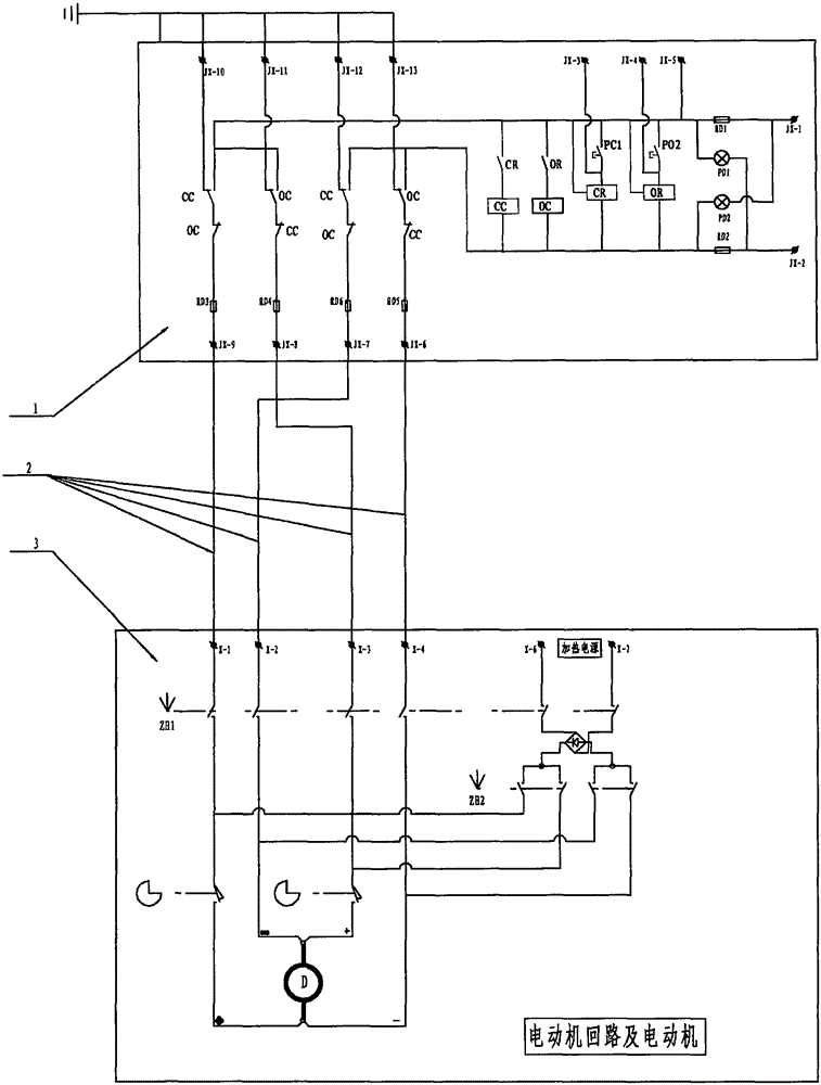
[0020] Specifically, such as figure 2 As shown, the power supply...


PUM


Abstract

The invention relates to a high-reliability remote control switching device. The high-reliability remote control switching device comprises a power supply controller, a control cable and a motor loop; the power supply controller (1) is arranged in a control room; the control cable (2) is a power transmission channel; the motor loop (3) is arranged in an electric operation mechanism box; a motor operates under command control of the power supply controller; the power supply controller comprises at least one set of contactors; normally open contacts of the contactors are connected with a power supply power line; normally closed contacts are grounded; coils of the contactors are controlled by input remote control signals; when the remote control signals are input, the normally open contacts are closed and the normally closed contacts are opened; power is supplied to the motor through the control cable; when the remote control signals are not input, the normally open contacts are opened and the normally closed contacts are closed and grounded; and thus, the control cable, the motor loop and the motor coil are grounded. According to the invention, false action or no action of the electric operation mechanism due to external electromagnetic interference can be avoided; and the operation reliability of a power grid or a contact network can be effectively increased.

Description

technical field [0001] The invention belongs to the technical field of electric power, and in particular relates to a high-reliability remote switch device. Background technique [0002] At present, in the ordinary railway and high-speed railway catenary and in the existing power grid, the opening or closing of a large number of high-voltage switches and high-voltage isolating switches is driven by the electric operating mechanism, and the electric operating mechanism completes the process of closing or opening. There are two ways, one is to send a power supply to the electric operating mechanism, and the remote control command controls the power supply to switch to the motor through the signal of the optical cable, so that the motor rotates forward or reverse, and realizes the opening or closing action. The second is to send a power supply to the electric operating mechanism, and control the switching of the power supply to the motor through the remote control cable, so tha...

Claims


Application Information

Patent Timeline
Patent Type & Authority Applications(China)
IPC IPC(8): H02J13/00
Inventor 葛柳明张臣义
Owner 北京华美煜力电力技术有限公司
Why Eureka
Try Eureka