Tire
A technology of tires and thermoplastic elastomers, applied in special tires, tires, tire parts, etc., can solve the problems of difficult stress and low cost, and achieve excellent durability
- Summary
- Abstract
- Description
- Claims
- Application Information
AI Technical Summary
Problems solved by technology
Method used
Image

Examples
no. 1 approach
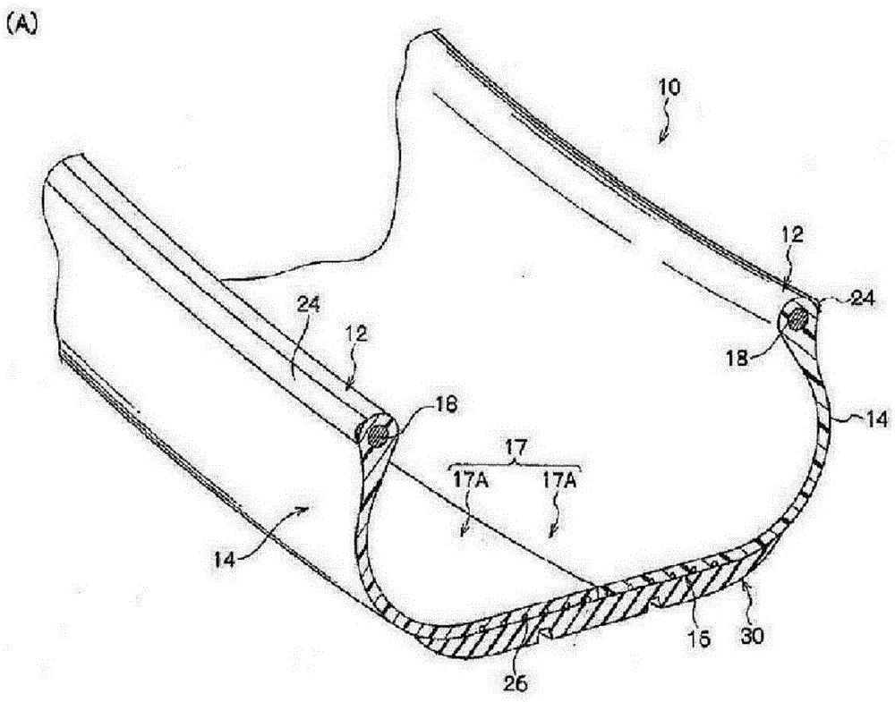
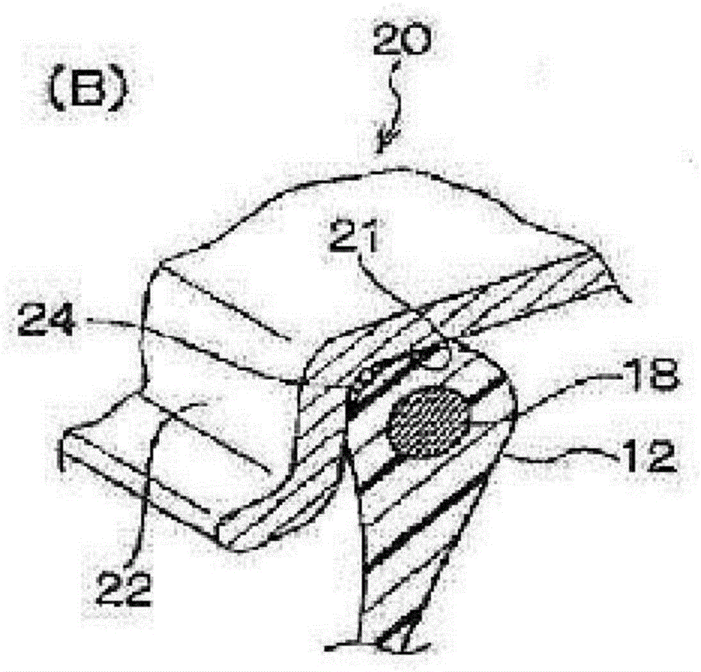
[0190] First, the edge reference Figure 1A and Figure 1B , the tire 10 according to the first embodiment of the present invention will be described. Figure 1A It is a perspective view showing a part of the cross section of the tire of the first embodiment. Figure 1B It is a cross-sectional view of the bead portion attached to the rim. Such as Figure 1A As shown, the tire 10 of the first embodiment has substantially the same cross-sectional shape as a conventional pneumatic tire made of general rubber.
[0191] The tire 10 according to the first embodiment of the present invention is provided with a tire casing 17, and the tire casing 17 includes a pair of bead portions 12 that are in contact with the bead seat 21 and the rim bead 22 of the rim 20. The sidewall portion 14 extending radially outward, and the crown portion (peripheral portion) 16 connecting the tire radially outer end of one sidewall portion 14 and the tire radially outer end of the other sidewall portio...
no. 2 approach
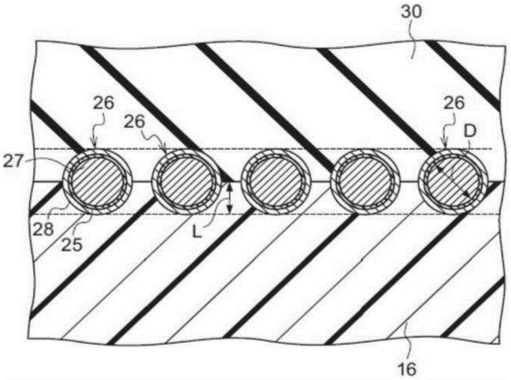
[0236] Next, edge reference Figure 4 Next, a tire according to a second embodiment of the present invention will be described. Figure 4 It is a cross-sectional view along the tire rotation axis showing a mode in which a reinforcing cord coating layer in which a reinforcing metal cord member is embedded is provided on the crown portion of a tire casing according to a second embodiment of the present invention.
[0237] Such as Figure 4 As shown, the tire according to the second embodiment of the present invention has a reinforcing cord coating layer 29 in which steel cords 27 (reinforcing metal cord members) are embedded on the surface of the crown portion 16 of the tire casing. A tread 30 is provided. The tire according to the second embodiment of the present invention has the same configuration as the first embodiment except for the above-mentioned points, and the same reference numerals are given to the same configurations as the first embodiment.
[0238] In the tire ...
Embodiment 1
[0260] According to the resin-coated cord forming process described above, a multifilament with an average diameter of φ1.15 mm (twisted yarn obtained by twisting a monofilament of φ0.35 mm (made of steel, strength: 280 N, elongation: 3%)) Hot-melt adhesive A-1 described in Table 1, which was heated and melted at 240°C, was attached so that the average layer thickness was 100 μm, and then covered with resin N-1 extruded from an extruder and cooled, thereby A reinforcing metal cord was obtained in which the outer periphery of the multifilament was coated with the adhesive layer-coating composition N-1 containing the hot-melt adhesive A-1.
[0261] Using the obtained reinforcing metal cords, a tire was formed by the same method as in the above-mentioned first embodiment. N-1 described in Table 1 was used as the tire frame forming material.
PUM
| Property | Measurement | Unit |
|---|---|---|
| thickness | aaaaa | aaaaa |
| softening point | aaaaa | aaaaa |
| melting point | aaaaa | aaaaa |
Abstract
Description
Claims
Application Information