
Fluid control valve and application thereof

A fluid control valve and valve control technology, applied in safety valves, balance valves, valve devices, etc., can solve the problems of resource waste, fluid volatilization, outlet blockage, etc., achieve large area and stroke, prevent liquid volatilization, and isolate air. the effect of exchange

Inactive Publication Date: 2015-12-23
SHANGHAI PINYI IND DESIGN
View PDF5 Cites 0 Cited by
  • Summary
  • Abstract
  • Description
  • Claims
  • Application Information

AI Technical Summary

Problems solved by technology

[0003] ① It is useless to completely isolate the passage between the fluid in the container and the outside air, resulting in problems such as fluid volatilization or air oxidation;
[0004] ②The pipeline between the fluid control valve and the fluid outlet is long. After the valve is closed, the remaining fluid in the pipeline will still flow slowly and dry up. If it is not used for a long time, the outlet will be blocked;
[0005] ③There is a lot of fluid in the fluid container that cannot be discharged after use, resulting in waste of resources and environmental pollution;
[0006] ④The existing mainstream valve body structure is relatively complex, and the manufacturing cost and maintenance cost are relatively high
The pressure-taking discharge valve body of the body wash and shampoo does not isolate the contact between the liquid and the air. When the air is dry for about 5 days, a dry solid substance will be formed at the outlet. After use, about 5% of the residue cannot be discharged, resulting in waste and pollution happen
Edible oil and soy sauce are basically still used in the traditional method of opening the cover → dumping → closing the cover, which is not convenient enough to operate and difficult to control the dosage

Method used


Image

  • Fluid control valve and application thereof
  • Fluid control valve and application thereof
  • Fluid control valve and application thereof

Examples


Embodiment Construction

[0034] Below in conjunction with accompanying drawing, the present invention will be further described as follows:

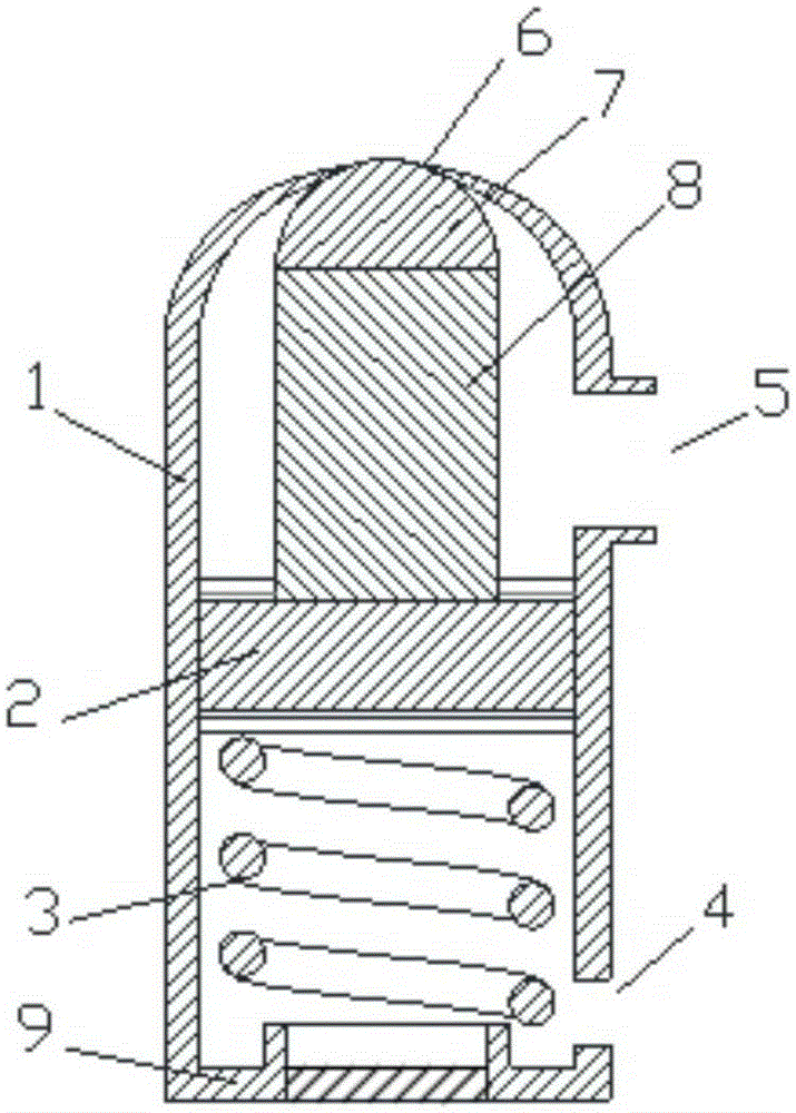
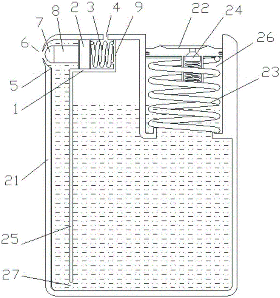
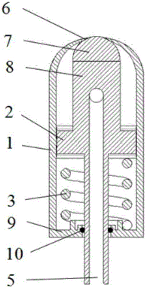
[0035] as attached figure 1 As shown, the fluid control valve of the present invention includes: a valve body 1, a valve stem 8 and a valve core 7. The inside of the valve body 1 is sealed and connected to a piston 2. The upper end of the piston 2 is connected to the valve stem 8, and the lower end thereof is connected to the spring 3. At one end, the top end of the valve rod 8 is provided with a valve core 7, and the other end of the spring 3 is connected to the bottom 9 of the valve body, and the bottom 9 of the valve body and the valve body 1 are integrally structured. The valve body 1 above the piston 2 is provided with a fluid inlet 5 and a fluid outlet 6 , the fluid outlet 6 is matched with a valve core 7 , and the valve core 7 is matched with the fluid outlet 6 . The valve body 1 between the piston 2 and the valve body bottom 9 is provided with an exhaus...


PUM


Abstract

The invention relates to a fluid control valve. The fluid control valve comprises a valve body (1), a valve rod (8) and a valve element (7), wherein a piston (2) is in sealing manner with the inner part of the valve body (1); the upper end of the piston (2) is connected with the valve rod (8) while the lower end of the piston (2) is connected with one end of a spring (3); the valve element (7) is arranged on the top end of the valve rod (8); the other end of the spring (3) is connected to the bottom part (9) of the valve body; a fluid inlet (5) and a fluid outlet (6) are formed in the valve body (1) on the piston (2); the fluid outlet (6) is in match with the valve element (7), and the valve element (7) is positioned in the fluid outlet (6). According to the fluid control valve, the valve body is small in size, simple in structure, low in cost, and easy to achieve high sealing performance so that fluid can be prevented from volatizing and the interchange of air can be avoided; after the fluid outlet of the valve is closed, extremely little fluid residues at the fluid outlet and can be slightly wiped.

Description

[technical field] [0001] The invention relates to the technical field of fluid control, in particular to a fluid control valve and its application. [Background technique] [0002] In the current application of fluid control valves: chemical industry, chemical experiments, daily life and many other aspects, there are two prominent problems in the existing fluid control methods: [0003] ① It is useless to completely isolate the passage between the fluid in the container and the outside air, resulting in problems such as fluid volatilization or air oxidation; [0004] ②The pipeline between the fluid control valve and the fluid outlet is long. After the valve is closed, the remaining fluid in the pipeline will still flow slowly and dry up. If it is not used for a long time, the outlet will be blocked; [0005] ③There is a lot of fluid in the fluid container that cannot be discharged after use, resulting in waste of resources and environmental pollution; [0006] ④ The structu...

Claims


Application Information

Patent Timeline
Patent Type & Authority Applications(China)
IPC IPC(8): F16K17/04F16K17/168F16J12/00
CPCF16J12/00F16K17/04F16K17/168
Inventor 李晓庆
Owner SHANGHAI PINYI IND DESIGN
Learn More