GB-SAR deformation monitoring method based on triple stepping

A GB-SAR and deformation technology, applied in the direction of measuring device, radio wave measurement system, radio wave reflection/re-radiation, etc., can solve the problems of low azimuth resolution, high cost of pulse SAR, rough deformation map, etc., to achieve improved Distance resolution and azimuth resolution, the effect of increasing the monitoring range

Inactive Publication Date: 2015-12-23
UNIV OF ELECTRONICS SCI & TECH OF CHINA
View PDF6 Cites 10 Cited by
  • Summary
  • Abstract
  • Description
  • Claims
  • Application Information

AI Technical Summary

Problems solved by technology

[0004] The difficulty of GB-SAR deformation monitoring radar lies in: (1) Affected by factors such as field operations, installation and cost, the track for placing the radar cannot be too long, but if the track is too short, the length of the synthetic hole will be small, the azimuth resolution will be low, and the azimuth resolution will be low. The size of the unit in the direction is large, resulting in a rough deformation map, which cannot reflect the specific deformation position
Reducing the radar wavelength can also improve the azimuth resolution, but if the wavelength is too short, it will be sensitive to meteorological conditions, reduce the measurement distance and increase the atmospheric phase error
(2) To improve the range resolution, a large signal bandwidth is required, and the cost of conventional pulse SAR is relatively high, and its imaging algorithm cannot be used for stepping frequency continuous wave radar
(3) The monitoring range is a fan-shaped area centered on the radar. Usually, the beam width of the antenna azimuth is only a few degrees, resulting in too small a monitoring area, and only strip area monitoring can be done.
Reducing the antenna size can increase the beam width. For example, when the beam width is 1 radian or 57.3°, the antenna size is only equivalent to the wavelength. Too small antenna size will result in reduced antenna gain and poor performance

Method used


Image

  • GB-SAR deformation monitoring method based on triple stepping
  • GB-SAR deformation monitoring method based on triple stepping
  • GB-SAR deformation monitoring method based on triple stepping

Examples


Embodiment Construction

[0021] How Radar Works and Design Constraints:

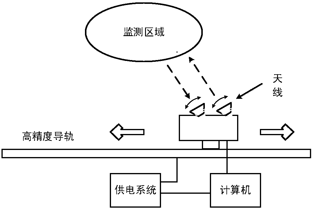
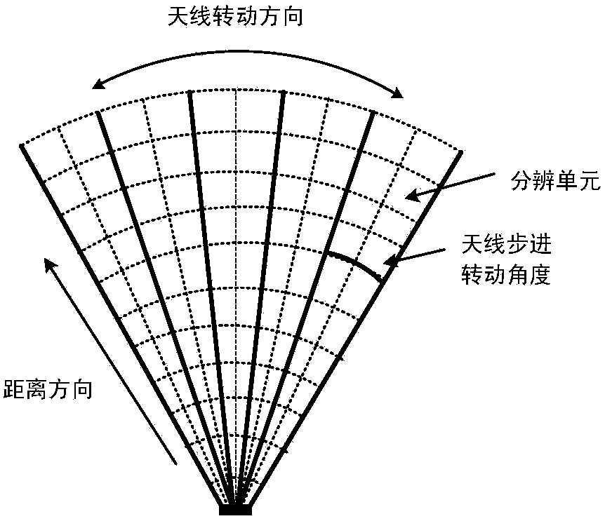
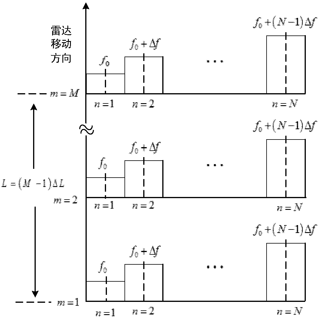
[0022] The radar is a step frequency continuous wave system, using independent transmitting antenna and receiving antenna, the antenna can be rotated in steps along the azimuth direction, and the whole radar is installed on a linear guide rail with a length of L, such as figure 1 shown. The monitoring area is centered on the radar with a radius of R max (Maximum operating range of the radar), the radar divides the monitoring area into several resolution units along the range and azimuth directions. The radar moves step by step according to the "stop-go-stop" mode on the guide rail, each time it moves a distance of ΔL, and then stops to send and receive a frame of SFCW signal, and the number of step frequency is N, such as image 3 shown. The carrier frequency of the first pulse of each frame signal is f c , the frequency step value is Δ f , the carrier frequency of the sub-monopulse is f n = f c +(n-1)Δf. The radar retur...


PUM


Abstract

The invention provides a GB-SAR deformation monitoring method based on triple stepping. According to radar system design, GB-SAR based on triple stepping is utilized for deformation measurement; for first stepping, stepped frequency continuous wave (SFCW) signals are employed to synthesize large signal bandwidth, isolation is improved through transceiver antenna separation; for second stepping, a radar device is mounted on a linear guide rail and does stepping motion in a stop-go-stop mode, orientation resolution is improved through relatively large aperture synthesis, signals are emitted and received by the radar device in stop periods, so a phase error caused by signal transceiving in motion periods is avoided; for third stepping, radar device antennas do stepping motion sequentially along the orientation, a relatively wide monitoring area is covered, and data at different antenna positions are spliced and are used for imaging processing. Imaging processing on acquired data is carried out based on echo signal characteristics of the GB-SAR system, compensation for an instantaneous slant range difference between pulses is not necessary, computational complexity is relatively low, and timeliness requirement of the GB-SAR system can be satisfied.

Description

technical field [0001] The invention relates to a synthetic aperture radar SAR imaging technology. Background technique [0002] Stepped Frequency Continuous Wave (Stepped Frequency Continuous Wave, SFCW) GB-SAR (Ground-Based SAR) is a ground-based synthetic aperture imaging radar placed on orbit, which obtains large bandwidth and high distance by continuously transmitting and receiving stepped frequency continuous wave signals Through the stepping movement of the radar on the guide rail, the large aperture and high azimuth resolution are synthesized, and the deformation or micro-displacement measurement value of the target is obtained through the imaging of the two movements for interference processing. Since the radar and the guide rail are installed on a fixed The position can be continuously measured with high precision to realize the monitoring of specific areas or targets, and early warning of possible natural disasters or infrastructure dangers. The radar system has ...

Claims


Application Information

Patent Timeline
Patent Type & Authority Applications(China)
IPC IPC(8): G01B15/06G01S13/90
Inventor 王洪李俊慧汪学刚
Owner UNIV OF ELECTRONICS SCI & TECH OF CHINA
Why Eureka
Try Eureka