
Computer vision based transparent medium refractivity measurement method

A computer vision and transparent medium technology, applied in the measurement of phase influence characteristics, etc., can solve the problems of cumbersome derivation process, difficult to obtain, special fiber material, etc., and achieve the effect of easy image acquisition process, automation and low price.

Inactive Publication Date: 2015-12-23
WUHAN UNIV OF TECH
View PDF11 Cites 6 Cited by
  • Summary
  • Abstract
  • Description
  • Claims
  • Application Information

AI Technical Summary

Problems solved by technology

This type of method is mainly applicable to the measurement of the refractive index of liquid or gas, and the derivation process is relatively cumbersome, and the optical fiber material is relatively special, so it is not easy to obtain

Method used


Image

  • Computer vision based transparent medium refractivity measurement method
  • Computer vision based transparent medium refractivity measurement method
  • Computer vision based transparent medium refractivity measurement method

Examples


Embodiment Construction

[0029] The present invention will be further described below in conjunction with specific examples and accompanying drawings.

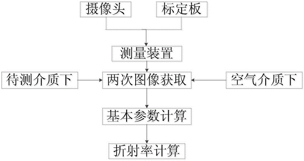
[0030] figure 2 It is a flow chart of the method of the present invention, a method for measuring the refractive index of a transparent medium based on computer vision, comprising the following steps:

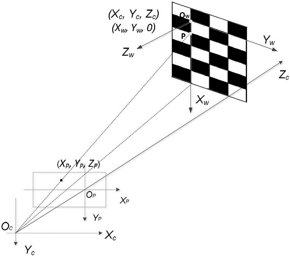
[0031] S1. Select a calibration board for calibration: use a camera and a calibration board. The calibration board is located within the range of the image captured by the camera and has a known size; respectively establish the camera coordinate system and the image coordinate system, and establish the relationship between the two coordinate systems.

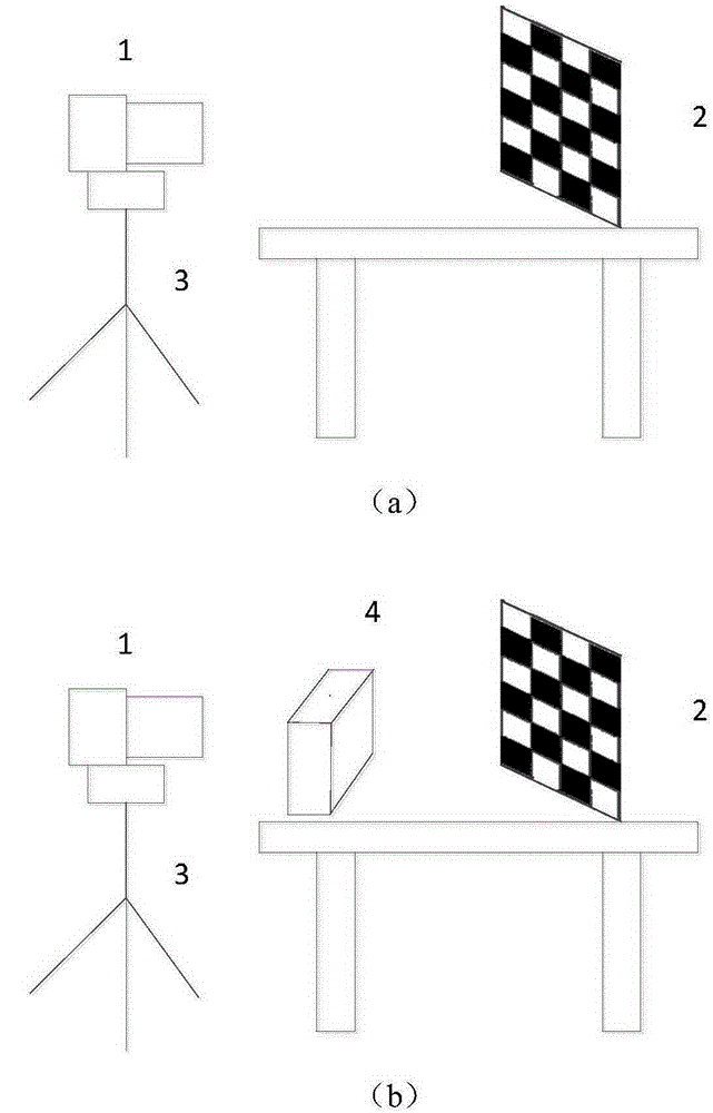
[0032] In this embodiment, the calibration board is a black and white checkerboard grid (selecting black and white grids can better identify and calculate, avoid denoising the image, and other patterns can also be used), and each grid is a square with a size of 3cm × 3cm (size For better calibration, t...


PUM


Abstract

The invention provides a computer vision based transparent medium refractivity measurement method. The method includes: selecting a camera and a calibration plate; establishing a camera coordinate system, an image coordinate system and a relationship of the two coordinate systems; conducting two image acquisition on the calibration plate with the camera, with one image acquisition carried out under the air medium, and the other carried out under the circumstance of placing a to-be-measured medium between the calibration plate and the camera; utilizing a pinhole camera model to calculate the depth information of a corner point under a camera coordinate system, the corner point corresponded included angle between a back projection ray and an optical axis, and the position change of the corner point in two images; measuring the thickness of the to-be-measured medium, deducing the refractivity calculation formula of the to-be-measured medium according to a pinhole imaging model and the Snell law of refraction, and introducing the calculation parameters to obtain the refractivity of the to-be-measured medium. The method provided by the invention realizes measurement of object refractivity only through two image acquisition on the calibration plate with the camera, greatly simplifies the process of calculation, simplifies the measurement steps, reduces the measurement cost, and has high calculation accuracy.

Description

technical field [0001] The invention relates to the fields of computer vision image data processing, camera model, three-dimensional reconstruction and optical measurement, in particular to a method for measuring the refractive index of a transparent medium based on computer vision. Background technique [0002] The ratio of the propagation speed of light in other media to the propagation speed in vacuum is called the refractive index. The phenomenon of refraction is ubiquitous in our daily life. At the same time, the phenomenon of refraction has an important impact on the research of computer vision, optical imaging, medicine and other fields. However, in practice, some objects cannot obtain accurate refractive indices because they are made of unknown materials or contain impurities. Therefore, it is of great significance to quickly and accurately calculate the refractive index of transparent objects. [0003] At present, the measurement methods of the refractive index are...

Claims


Application Information

Patent Timeline
IPC IPC(8): G01N21/41
Inventor 胡钊政李祎承胡月志李京
Owner WUHAN UNIV OF TECH
Learn More