A method of ionospheric vertical profile modeling and parameter inversion

A vertical profile, parameter inversion technology, applied in electrical digital data processing, special data processing applications, instruments, etc., can solve problems such as large differences, not considering the smoothness of layer-to-layer connections, and improve inversion accuracy. and stability effects

Inactive Publication Date: 2018-07-27
THE 22ND RES INST OF CHINA ELECTRONICS TECH GROUP CORP
View PDF3 Cites 0 Cited by
  • Summary
  • Abstract
  • Description
  • Claims
  • Application Information

AI Technical Summary

Problems solved by technology

[0003] At present, the commonly used vertical ionogram inversion method is the ionospheric parameter inversion method based on the idea of ​​the model method. Among them, Huang Xueqin et al. disclosed a method for inverting the ionospheric profile based on the shifted Chebyshev polynomial model , in this method, the F layer is modeled as a shifted Chebyshev polynomial, and the polynomial coefficients that satisfy the best agreement between the calculated virtual height and the measured virtual height in the sense of least squares are solved to determine the ionospheric profile. F is evident in the wave trace 1 In the case of layer tracing, some improvements have been made on the model, that is, F 1 layers and F 2 Layers are represented by different shifted Chebyshev polynomials, but this method is more suitable for F 1 When the layer is fully developed, for F 1 When the layer is not fully developed, the vertical ionogram synthesized based on the inversion results and the measured ionogram are at F 1 There is a large difference near the adjacent frequency of the layer. In addition, the smoothness of the layer-to-layer connection is not considered, which is also the shortcoming of this method.

Method used


Image

  • A method of ionospheric vertical profile modeling and parameter inversion
  • A method of ionospheric vertical profile modeling and parameter inversion
  • A method of ionospheric vertical profile modeling and parameter inversion

Examples


Embodiment 1

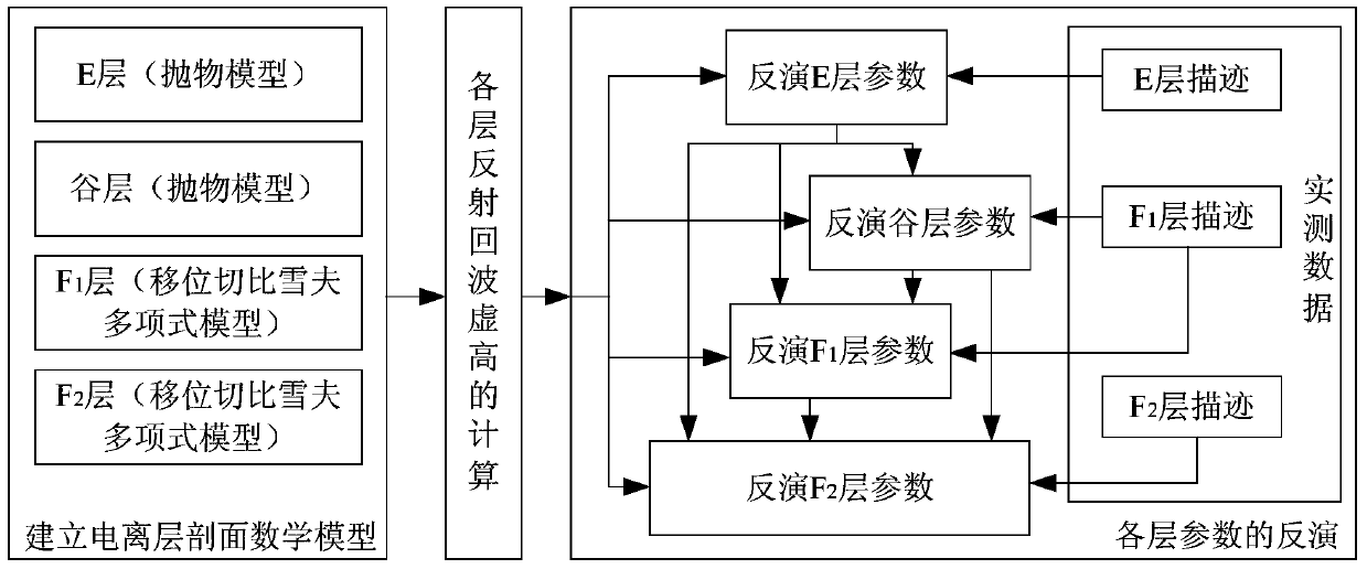
[0043] Example 1, such as figure 1 As shown, this embodiment discloses a method for modeling and parameter inversion of the vertical profile of the ionosphere, including the following steps:

[0044] (1) Establish a mathematical model of the ionospheric profile:

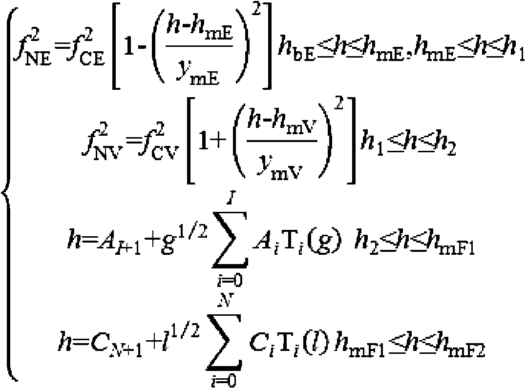
[0045] The present invention is based on the thought of pattern method, ionosphere is modeled as including E layer, valley layer, F 1 Layer, F 2 The four-layer model of the layer, the E layer and the valley layer profile are represented by the parabolic model, and the F 1 layers and F 2 The layer profile is represented by the shifted Chebyshev polynomial model, and the ionospheric electron concentration profile has the form shown in formula (1):

[0046]

[0047] The connection point between the E layer and the valley layer is located at the peak height h of the E layer mE , Valley and F 1 The connection point of the layer is at height h 2 and at height h 2 The plasma frequency at is equal to the critical ...


PUM


Abstract

The invention discloses an ionosphere vertical section modeling and parameter inversion method. The method comprises the following steps: 1, modeling an ionosphere into a four-layer model including an E layer, a valley layer, an F<1> layer and an F<2> layer; 2, deducing a calculation formula of an echo virtual height of each layer based on the established ionosphere model; and 3, performing inversion of an ionosphere parameter of each layer by using measured ionogram data in combination with a calculation result of the echo virtual height of each layer. The ionosphere vertical section modeling and parameter inversion method disclosed by the invention is based on a vertical exploration ionogram inversion method for optimizing F<1> layer parameters and F<2> layer parameters on the basis of the constraint of a shifted Chebyshev polynomial model, namely, echo tracing data in a high region in the F<1> layer are selected after a valley parameter is obtained, and an F<1> layer section polynomial coefficient is calculated under the condition of ensuring continuously smooth constraint of the section. The method is suitable for effectively improving the inversion accuracy and stability under the situation that the F<1> layer is not developed fully.

Description

technical field [0001] The invention relates to the field of ionosphere research and application, in particular to an ionosphere vertical profile modeling and parameter inversion method. Background technique [0002] Ionospheric vertical detection (referred to as vertical measurement) can obtain vertical measurement ionograms that reflect the relationship between the false height and frequency of the ionosphere. The so-called false height is essentially a measure of the propagation time of electromagnetic waves. The time elapsed after arriving at the vertical survey receiver multiplied by the speed of light is called false height. The false height obtained by the vertical survey is not the real reflection height of the electromagnetic wave in the ionosphere, and the acquisition of the real reflection height requires the inversion of the vertical survey ionogram, that is, the inversion of the ionospheric profile by using the vertical survey ionogram frequency-false height tra...

Claims


Application Information

Patent Timeline
Patent Type & Authority Patents(China)
IPC IPC(8): G06F19/00
Inventor 蔚娜柳文冯静杨龙泉鲁转侠师燕娥郭文玲
Owner THE 22ND RES INST OF CHINA ELECTRONICS TECH GROUP CORP
Why Eureka
Try Eureka