Supercharge Your Innovation With Domain-Expert AI Agents!

Inclined gap type reactor iron core structure and production process thereof

A technology of iron core structure and reactor, which is applied in the direction of transformer/inductor magnetic core, circuit, electrical components, etc., can solve the problems of easy displacement and vibration, increased loss of accessories, etc., and achieve the reduction of magnetic voltage drop, noise and The effect of reduced loss and ingenious and practical structure

Inactive Publication Date: 2015-12-23
GUANGDONG NRE TECH
View PDF10 Cites 3 Cited by
  • Summary
  • Abstract
  • Description
  • Claims
  • Application Information

AI Technical Summary

Problems solved by technology

The gaps of traditional reactor iron cores are perpendicular to the direction of the magnetic circuit. In this arrangement, the silicon steel sheet is prone to displacement and vibration in the alternating magnetic field, resulting in noise; secondly, due to the magnetic resistance at the air gap Much larger than the silicon steel sheet, the energy of the magnetic circuit is concentrated at each air gap, resulting in more additional loss due to the leakage of magnetic flux and the leakage of the magnetic force line at each air gap. When the magnetic force line passes through the coil, the loss of the attachment of the coil will increase significantly

Method used


Image

  • Inclined gap type reactor iron core structure and production process thereof
  • Inclined gap type reactor iron core structure and production process thereof
  • Inclined gap type reactor iron core structure and production process thereof

Examples


Embodiment 1

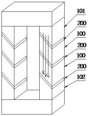
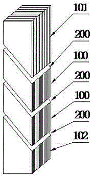
[0021] This embodiment discloses an inclined-plane air-gap reactor core structure, such as figure 1 As shown, it includes at least a plurality of silicon steel pieces 100 arranged in a row. The silicon steel piece 100 is composed of a plurality of stacked silicon steel sheets. An air gap is formed between two adjacent silicon steel pieces 100, and an air gap plate 200 is arranged in the air gap. , the air-gap plate 200 is bonded and fixed to the silicon steel piece by an adhesive. In this embodiment, the air gap is set obliquely, the angle between the air gap and the magnetic circuit is less than 180° and not equal to 90° (the arrow in the figure indicates the direction of the magnetic circuit), the air gap plate 200 is placed in the air gap, and the air gap plate 200 Tilt setting.

[0022] The silicon steel piece in this embodiment is provided with two kinds of shapes, see figure 1 and 2 , the silicon steel pieces on the upper and lower sides (namely 101 and 102) are arran...

Embodiment 2

[0030] This embodiment is basically the same as Embodiment 1, except that the air-gap plate of this embodiment uses a fiber insulation board with a rough surface, and the surface of the fiber insulation board has numerous fine burrs.

Embodiment 3

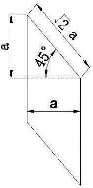
[0032] This embodiment is basically the same as Embodiment 2, the difference is that the angle between the air gap and the magnetic circuit in this embodiment is 45°, see image 3 , the area of ​​the air gap is 1.414 times larger than the traditional one.


PUM

PropertyMeasurementUnit
Angleaaaaaaaaaa

Abstract

The invention discloses an inclined gap type reactor iron core structure and a production process thereof. The iron core structure comprises at least two silicon steel elements, wherein each silicon steel element comprises a plurality of laminated silicon steel sheets, the silicon steel sheets are distributed, a gap is formed between adjacent two silicon steel sheets, a gap plate is arranged in the gap and bonded and fixed with the silicon steel element by an adhesive, the gap is formed in an inclined way, an included angle between the gap and a magnetic path is less than 180 degrees and is not equal to 90 degrees, and the gap plate is arranged in the gap and reclines. The iron core structure is ingenious and practical; with the gap formed in an inclined way, the bonding area of the silicon steel elements and the area of the gap plate are expanded, the magnetic flux density of the gap is reduced by 41.4%, the magnetic potential drop and leakage flux radiation quantitiesof the gap are reduced, and the noise and the loss of the gap are substantially reduced.

Description

technical field [0001] The invention relates to the field of iron core reactors, in particular to an inclined plane air gap type reactor iron core structure and a production process thereof. Background technique [0002] In modern industry, as an indispensable and important component in the field of power electronics, iron core reactors are widely used in harmonic suppression circuits or power compensation circuits of power transmission grids, and are also widely used in electric locomotives, marine ships, new energy, Filter circuits, resonant circuits or current limiting circuits in UPS and other fields. In practical applications, the current flowing through the core reactor is not only a 50Hz or 60Hz sine wave current, but often contains rich harmonics (150Hz~2kHz), high frequency modulation waves (1kHz~20kHz), etc. Due to the structure of the iron core reactor and its application limitations, the reactor will produce various noises, abnormal sounds, vibrations, etc. in a...

Claims


Application Information

Patent Timeline
IPC IPC(8): H01F27/26H01F27/245H01F3/14
Inventor 冉瑞刚李裕宝
Owner GUANGDONG NRE TECH
Features
  • R&D
  • Intellectual Property
  • Life Sciences
  • Materials
  • Tech Scout
  • Unparalleled Data Quality
  • Higher Quality Content
  • 60% Fewer Hallucinations
Learn More