
Lightning conductor high-voltage power-obtaining system and power-obtaining method

A technology for lightning protection wires and electrical systems, which is applied in the installation of electromagnetic wave systems, electrical components, and cables, and can solve problems such as power supply, equipment maintenance costs, and inability to achieve continuous and uninterrupted power supply

Inactive Publication Date: 2015-12-23
PUYANG POWER SUPPLY COMPANY STATE GRID HENAN ELECTRIC POWER +1
View PDF3 Cites 6 Cited by
  • Summary
  • Abstract
  • Description
  • Claims
  • Application Information

AI Technical Summary

Problems solved by technology

Due to the limitation of energy conversion efficiency, climate environment and cost, solar power supply cannot fully meet the equipment's requirements for all-weather and long-term stable performance, so batteries have to be added to store electric energy
However, because the life of the battery itself is generally only 2 to 3 years, the maintenance cost of the equipment increases, and this power supply method cannot achieve continuous and uninterrupted power supply, so it cannot meet the actual needs, making it difficult to popularize the high-voltage transmission line to realize the online real-time monitoring function.
[0004] In addition, with the development of technology, there are more and more electrical equipment working on high-voltage transmission lines, such as line equipment anti-theft devices, line inspection robots, live working robots, etc., and there are also power supply problems

Method used


Image

  • Lightning conductor high-voltage power-obtaining system and power-obtaining method
  • Lightning conductor high-voltage power-obtaining system and power-obtaining method
  • Lightning conductor high-voltage power-obtaining system and power-obtaining method

Examples


Embodiment Construction

[0022] The following will clearly and completely describe the technical solutions in the embodiments of the present invention with reference to the accompanying drawings in the embodiments of the present invention. Obviously, the described embodiments are only some of the embodiments of the present invention, not all of them. Based on the embodiments of the present invention, all other embodiments obtained by persons of ordinary skill in the art without making creative efforts belong to the protection scope of the present invention.

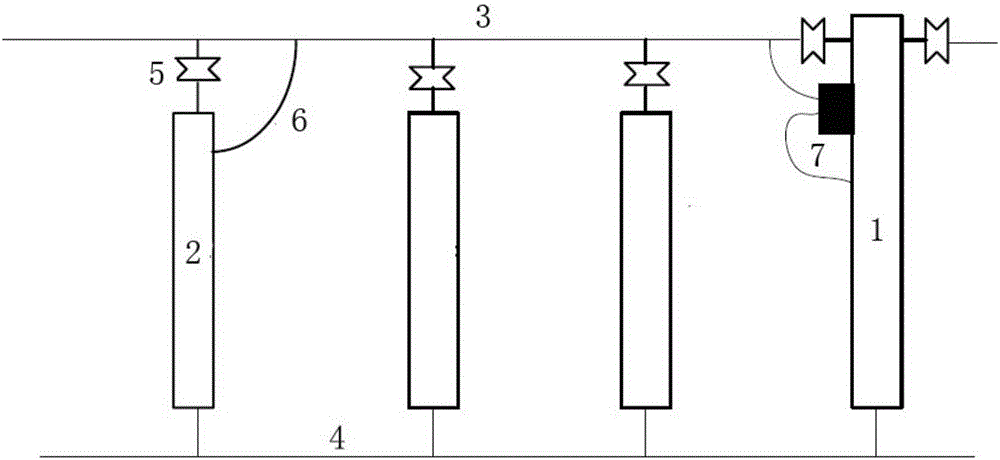
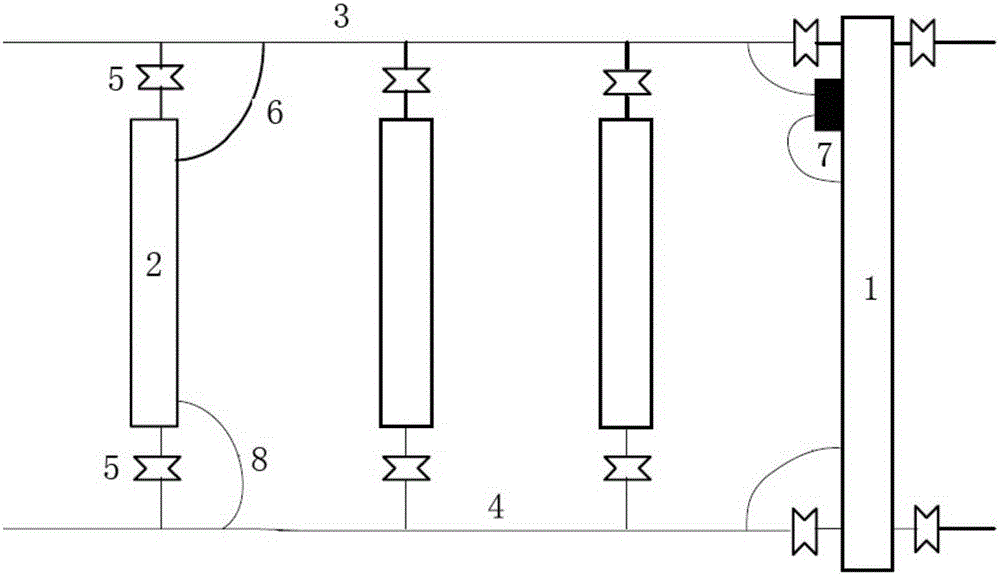
[0023] Such as figure 1 and 2 As shown, a lightning protection line high-voltage power-taking system includes two first towers 1 and second towers 2 with a distance of 2.5Km to 3Km. The first tower 1 and the second tower 2 are connected with a first ground wire 3, The second ground wire 4, the gap insulator 5 is arranged between the first ground wire 3 and the first pole tower 1 and the second pole tower 2, the first ground wire 3 is connected w...


PUM


Abstract

The invention provides a lightning conductor high-voltage power-obtaining system and a power-obtaining method, wherein the power is uninterruptedly obtained from a high-voltage line to power up power equipment on the power transmission line. The lightning conductor high-voltage power-obtaining system comprises a first tower pole and a second power pole, wherein the spacing between the two power poles is 2.5-3.5 km. The first tower pole and the second power pole are connected with a first ground wire and a second ground wire. A gap insulator is arranged between the first ground wire and the first and second tower poles. The first ground wire is connected with the second tower pole via a first grounding drainage thread. The first tower pole, the first ground wire, the second tower pole and the second ground wire together form a loop. An electromagnetic induction power-obtaining supply is arranged in the loop. According to the technical scheme of the invention, the power is obtained from a lightning conductor by the electromagnetic induction power-obtaining supply, so that the system is free from being influenced by the weather and the temperature. By means of the system, the all-weather, stable and reliable uninterrupted power supply is realized under various harsh weathers and in different working environments. Meanwhile, the system is maintenance-free for a long period of time and can overcome the defects of solar power supply mode and the like.

Description

technical field [0001] The invention relates to a high-voltage line power-taking device, in particular to a system for taking power from a high-voltage line lightning protection line. Background technique [0002] With the rapid development of the national economy, all walks of life have an increasing demand for power, and the requirements for power quality (such as stability and uninterrupted) are also getting higher and higher. Therefore, the safety and stability of new high-voltage transmission lines and supporting equipment, which are the lifelines of power systems, are particularly important. As the complexity of the transmission system increases and the number of protection and monitoring devices increases, the demand for DC power in the middle of the line increases. [0003] The voltage level requirements of this type of power supply are not high, but the requirements for uninterrupted power supply reliability are relatively high. At present, most of the power suppl...

Claims


Application Information

Patent Timeline
IPC IPC(8): H02G13/00H02G7/22H02J17/00
Inventor 赵庆喜黄桥林孟凡众郭彦朝盛从兵李玉伟郭彦辉
Owner PUYANG POWER SUPPLY COMPANY STATE GRID HENAN ELECTRIC POWER
Learn More