Grain noise detection fixture, device and method

A particle noise and detection fixture technology, applied in the direction of electrical components, electrical components, etc., can solve the problems of inability to realize particle noise detection and lower product qualification rate

Active Publication Date: 2015-12-23
NO 47 INST OF CHINA ELECTRONICS TECH GRP
View PDF3 Cites 4 Cited by
  • Summary
  • Abstract
  • Description
  • Claims
  • Application Information

AI Technical Summary

Problems solved by technology

[0003] In the past, the particle noise control of electronic products focused on the detection of redundant residues in sealed circuits, and the detection of particle noise before circuit sealing could not be realized.
However, once the circuit is sealed, it cannot be disassembled (once it is disassembled, it becomes a waste product). Therefore, after the sealing of the circuit with an unsatisfactory excess control level, it often fails to pass the particle noise in the screening assessment. Detection and become waste products, thereby reducing the pass rate of products

Method used


Image

  • Grain noise detection fixture, device and method
  • Grain noise detection fixture, device and method
  • Grain noise detection fixture, device and method

Examples


Embodiment Construction

[0033] Below in conjunction with accompanying drawing, invention is described in further detail.

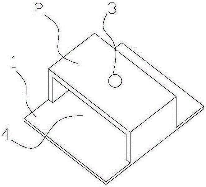
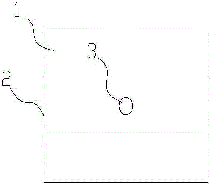
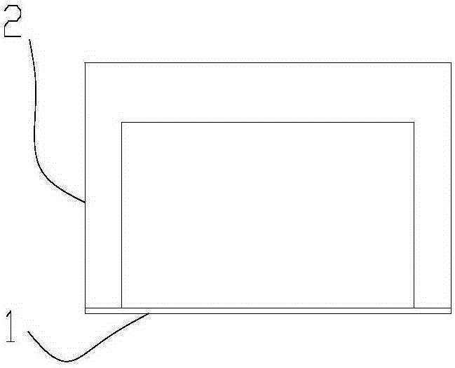
[0034] Figure 1~4 A particle noise detection jig according to an embodiment of the present invention is schematically shown. The fixture includes a base 1, a clamping frame 2 integrally formed with the base located on one side of the base 1, and the clamping frame 2 and the base 1 are enclosed to form a space for accommodating the component to be detected (for example, a circuit to be detected) The cavity 4 and the clamping frame 2 are provided with one or more fastener mounting holes 3 communicating with the cavity 4, and the fastener mounting holes 3 are bolt holes.

[0035] In practical application, place the component to be tested in the cavity 4, screw the bolts into the cavity 4 through the bolt holes until the bolts withstand the component to be tested, and then properly tighten the bolts to fasten the component to be tested. The operation is simple and convenient, and ...


PUM


Abstract

The invention provides a grain noise detection fixture, which comprises a base, and a clamping frame on one side of the base and integrally formed with the base. The clamping frame and the base are enclosed to form a cavity for accommodating a to-be-detected element. The clamping frame is provided with a fastener mounting hole in communication with the cavity. The invention also provides a grain noise detection device provided with the above grain noise detection fixture, and a grain noise detection method. The method comprises the steps of a1, removing surplus materials in a to-be-detected circuit; a2, covering a circuitron cap of the to-be-detected circuit onto a tube socket of the to-be-detected circuit without packaging the circuit; a3, fastening the to-be-detected circuit with the circuitron cap covered thereon into the fixture; a4, placing the fixture onto a grain noise tester for noise detection. By means of the grain noise detection fixture, the grain noise detection device and the grain noise detection method, the to-be-detected circuit can be pre-detected before being packaged.

Description

technical field [0001] The invention relates to the field of electronic product production, in particular to a jig, device and method for particle noise detection of electronic packaging products. Background technique [0002] The particle impact noise detection test is an effective means of redundant inspection, which is used to detect the redundant loose particles in the packages of electronic components such as integrated circuits, transistors, capacitors, and relays in aviation / aerospace / military fields. The principle is to use a vibrating table to generate a series of specified mechanical shocks and vibrations, through which the particles bound in the product (ie excess) are loosened, and then through a certain frequency of vibration, the excess is displaced in the system. The displacement process of the mobile excess in the product is a random combination process of the sliding process and the impact process of the excess relative to the product shell. During this pro...

Claims


Application Information

Patent Timeline
Patent Type & Authority Applications(China)
IPC IPC(8): H05K13/08
Inventor 赵鹤然田爱民张斌刘庆川刘洪涛
Owner NO 47 INST OF CHINA ELECTRONICS TECH GRP
Why Eureka
Try Eureka