Eureka AIR delivers breakthrough ideas for toughest innovation challenges, trusted by R&D personnel around the world.

Application dispenser for at least one component

A dispenser, all-in-one technology, applied in the field of adjustable dosing and/or mixing dispensers, able to solve problems such as insufficient supply action, to achieve the effect of preventing water loss, preventing excessive pump load, fast application effect

Active Publication Date: 2015-12-23
格哈德·布鲁格
View PDF6 Cites 4 Cited by
  • Summary
  • Abstract
  • Description
  • Claims
  • Application Information

AI Technical Summary

Problems solved by technology

However, the supply is not sufficient for oily or pasty substances that are often used in care products or adhesives

Method used


Image

  • Application dispenser for at least one component
  • Application dispenser for at least one component
  • Application dispenser for at least one component

Examples


Embodiment Construction

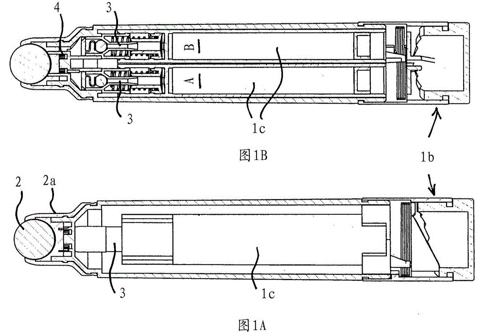
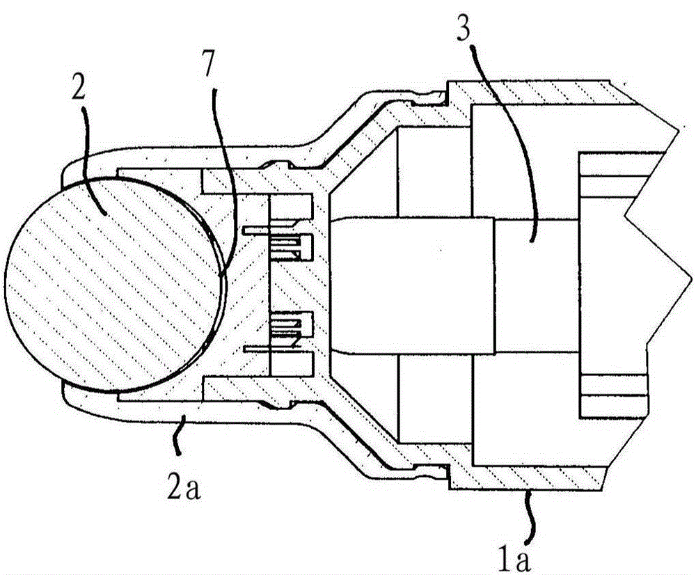
[0017] figure 1 The application dispenser 1 is shown, which appears to resemble a cylindrical pin. The application dispenser comprises a top-mounted rotating member 2 configured in particular as a ball to assist in the application of at least one ingredient, eg for lipstick or similar cosmetic products comprising two or more ingredients. The swivel part 2 protrudes here beyond a groove 2 a which is applied to the housing 1 a of the application dispenser 1 . An adjustment device 1b configured like a rotary knob is provided at the bottom of the housing 1a, by means of which the volume ratio of the two components can be adjusted by means of wedge-shaped parts (see Figure 1A and Figure 1B ). This adjusting device is described in more detail in the applicant's application DE 20 2012 006 466.5 and is therefore omitted here.

[0018] The ingredients are obtained from a schematically shown cylinder 1c (see especially Figure 1B ) is supplied to the rotating part 2 by means of c...


PUM


Abstract

In order to provide a simple design of an application dispenser for at least one component, in particular for an adjustable dosing and / or mixing dispenser, having a rotational body, in particular a ball for applying the component (s), it is proposed that a pump (3) conveys the components (A and / or B) to the rotational body (2) by the application of pressure.

Description

technical field [0001] The invention relates to an application dispenser for at least one ingredient, in particular for an adjustable dosing and / or mixing dispenser, according to the features of the preamble of claim 1 . Background technique [0002] Dispensers of this type are commonly used in cosmetic products, such as lipsticks, where conditioning ingredients are added to the lipsticks. For this purpose, until now, static mixers have often been used, in which the components are introduced into a helical tube and thus mixed. A disadvantage here, however, is that a significantly greater residual quantity remains in the mixer, so that, for example, when the dosing ratio changes, multiple strokes of the dosing distributor are required in order to finally achieve the desired mixing ratio. Since ingredients of this type can be very expensive, it is desirable that such disadvantages be substantially avoided. Also, the mixture may harden or become deactivated in the static mixe...

Claims


Application Information

Patent Timeline
Patent Type & Authority Applications(China)
IPC IPC(8): A45D34/04
CPCA45D2200/056A45D2200/058B05B11/0064B05B11/0038A45D34/041B01F25/4414B01F33/50112B01F35/522B01F35/831B05B11/1004B05B11/1083B05B11/1084A45D40/24
Inventor 格哈德·布鲁格
Owner 格哈德·布鲁格
Why Eureka
Eureka Blog
Learn More