
Corrugated spring for a torsional vibration damper

A technology of torsional shock absorber and wave spring, applied in the direction of spring, spring/shock absorber, cup spring, etc., can solve problems such as affecting the structural space of the clutch disc and requiring axial structural space, etc.

Inactive Publication Date: 2015-12-23
ZF FRIEDRICHSHAFEN AG
View PDF6 Cites 2 Cited by
  • Summary
  • Abstract
  • Description
  • Claims
  • Application Information

AI Technical Summary

Problems solved by technology

[0005] However, as a comparison of these two systems shows, it is not possible to use this type of wave spring in the radially staggered multi-stage torsional damper described above, because the radially inwardly placed spring groups set At the mounting point of the wave spring
Nevertheless, for the arrangement of the wave springs, additional radial installation space must be provided either radially inwardly or radially externally, which overall adversely affects the installation space of the clutch disc
Alternatively, the wave springs can be placed outside the pressure spring plane, however this may require axial construction space and is likewise undesirable

Method used


Image

  • Corrugated spring for a torsional vibration damper
  • Corrugated spring for a torsional vibration damper
  • Corrugated spring for a torsional vibration damper

Examples


Embodiment Construction

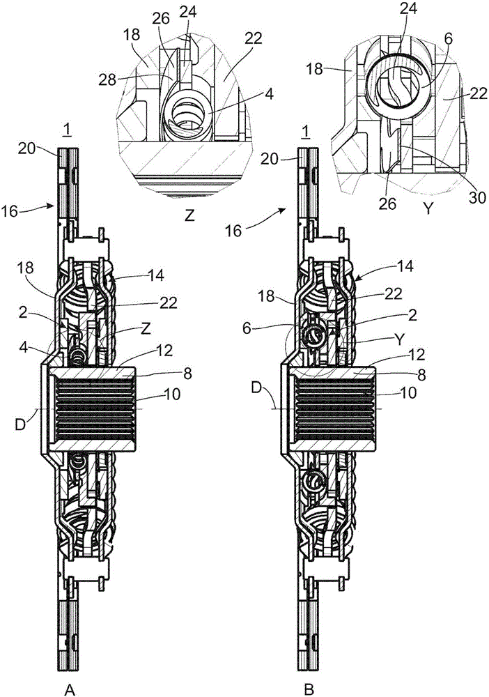
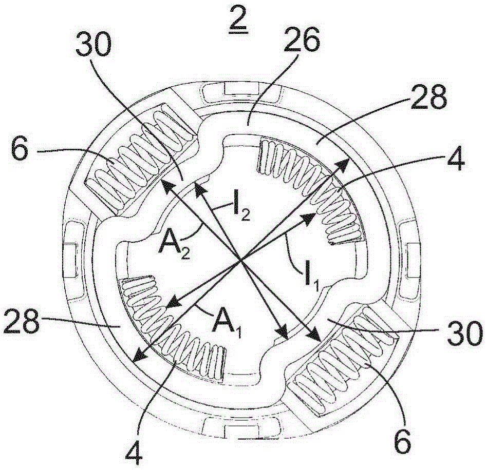
[0034] figure 1 A schematic sectional view of a clutch disk 1 according to the invention with a torsional vibration damper 2 according to the invention is shown, wherein sub-figure A shows the radially inner second part of the torsional vibration damper 2 according to the invention. A sectional view of a spring set 4 , and sub-figure B shows a sectional view of its radially outer second spring set 6 . In this case, the radially inner spring set 4 defines a first pre-damper stage, and the radially outer spring set 6 defines a second pre-damper stage.

[0035] As is generally known, the clutch disk 1 is configured concentrically with respect to the axis of rotation D and has a hub 8 with internal toothing 10 for a non-rotatable mounting on a transmission shaft (not shown). On the outer circumference, the hub 8 has an external toothing 12 which carries the elements of the torsional vibration damper 2 for the idling system, the main torsional vibration damper 14 and the clutch di...


PUM


Abstract

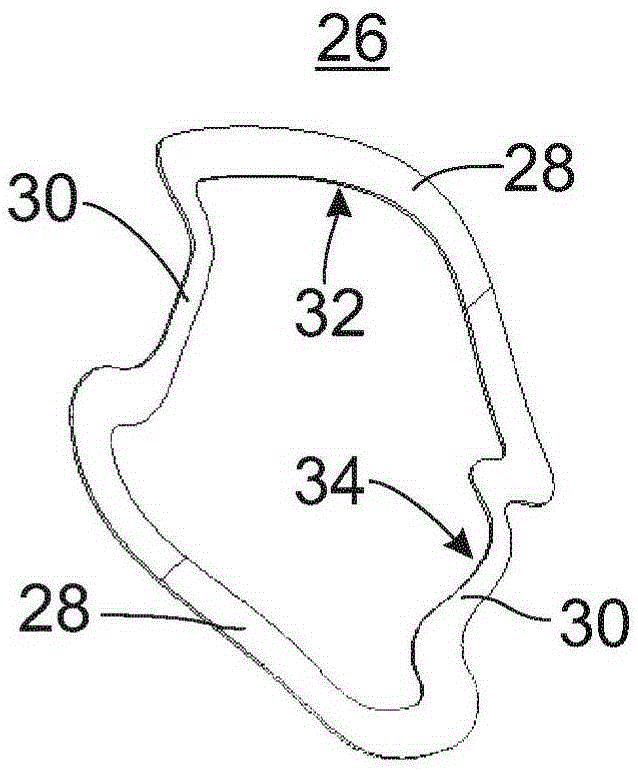
The invention relates to a corrugated spring (26), in particular for a torsional vibration damper (2) for a clutch disc (1), said corrugated spring (26) being essentially annular and has at least one first wave crest (32) and a second wave crest (34), the first wave crest (32) being arranged in a first corrugated spring region (28) having a first outer diameter (A1) and the second wave crest (34) being arranged in a second corrugated spring region (30) having a second outer diameter (A2) which is different from the first outer diameter (A1). The invention also relates to a torsional vibration damper (2) comprising said type of corrugated spring (26) and a clutch disc (1) comprising said type of torsional vibration damper (2).

Description

technical field [0001] The invention relates to a wave spring for a torsional vibration damper, in particular for a clutch disk, which is substantially annular and has at least one first and second peak. It also relates to a torsional vibration damper with such a wave spring and a clutch disk with such a torsional vibration damper. Background technique [0002] Engines in modern drive trains have high rotational irregularities. Therefore, in order to allow comfortable torsional vibration damping (torsional vibration damping), either a dual-mass flywheel or a torsionally damped clutch plate with several successively acting characteristic curve stages is used. Since rotational inhomogeneities occur especially at low rotational speeds, the clutch disk is designed in particular with a torsional vibration damper, which acts in the low-load range, especially during idling operation. In this case, torsional vibration dampers are known in which two preliminary damping characterist...

Claims


Application Information

Patent Timeline
Patent Type & Authority Applications(China)
IPC IPC(8): F16F15/129F16F1/32
CPCF16F15/1292F16F1/328
Inventor P·汉德里克F·科莱克
Owner ZF FRIEDRICHSHAFEN AG
Learn More