Ultrasonic probe calibration phantom and system as well as ultrasonic probe calibration method

一种超声探头、标定方法的技术,应用在超声图像领域,能够解决标定精度下降、N形目标三维坐标误差增大、共面性丢失等问题,达到提高实用性、避免意外抖动误差的效果

Active Publication Date: 2015-12-30
SHENZHEN INST OF ADVANCED TECH CHINESE ACAD OF SCI
View PDF4 Cites 18 Cited by
  • Summary
  • Abstract
  • Description
  • Claims
  • Application Information

AI Technical Summary

Problems solved by technology

However, the sound field of the ultrasonic probe diffuses as the scanning depth increases, and the ultrasonic imaging plane is not an ideal geometric plane
The imaging surface with a certain thickness intersects the linear target, and the projection of the emitting target on the ideal imaging plane is not comparable to a point, thus forming a linear or even arc-shaped bright spot feature point. However, this spot is picked up manually or automatically. There are large errors and uncertainties in the coordinates of the mark points, which causes the error in the three-dimensional coordinate reconstruction calculation of the N-shaped target to increase, resulting in the loss of the original coplanarity in this process, which in turn causes the decline in calibration accuracy.

Method used


Image

  • Ultrasonic probe calibration phantom and system as well as ultrasonic probe calibration method
  • Ultrasonic probe calibration phantom and system as well as ultrasonic probe calibration method
  • Ultrasonic probe calibration phantom and system as well as ultrasonic probe calibration method

Examples


Embodiment Construction

[0045] In order to facilitate the understanding of the present invention, the present invention will be described more fully below with reference to the associated drawings. Preferred embodiments of the invention are shown in the accompanying drawings. The above are only preferred embodiments of the present invention, and are not intended to limit the patent scope of the present invention. Any equivalent structure or equivalent process transformation made by using the description of the present invention and the contents of the accompanying drawings, or directly or indirectly used in other related technical fields , are all included in the scope of patent protection of the present invention in the same way.

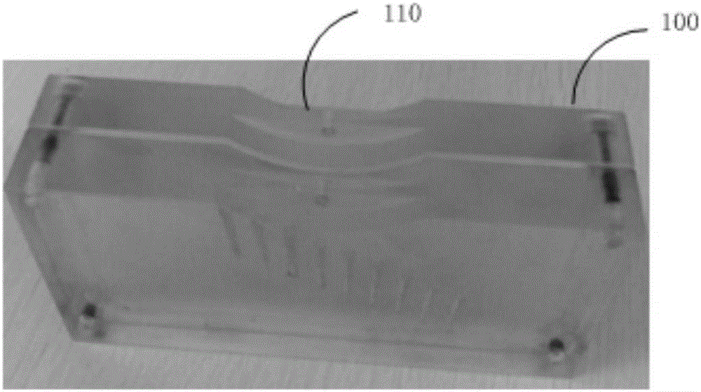
[0046] see figure 2 , the embodiment of the present invention provides an ultrasonic probe calibration phantom 100, a concave groove 110 is opened in the middle of the upper surface, and several tapered holes (not shown in the figure) are opened on one side of the phant...


PUM


Abstract

The invention provides an ultrasonic probe calibration phantom and system. A concaved groove is formed in the middle position of the upper surface of the ultrasonic probe calibration phantom, a plurality of taper holes are formed in the side surface of the ultrasonic probe calibration phantom, a two-dimensional ultrasonic probe is fixedly connected in the concave groove, NDI puncture probes are inserted into the taper holes, and tip ends of the NDI puncture probes can be acquired through ultrasound images. According to the ultrasonic probe calibration system adopting the structure, a neutral surface of the ultrasonic plane can just pass by the neutral surface of the ultrasonic probe calibration phantom along the middle seams, and the neutral surface of the ultrasonic plane just uses the tip ends of the NDI puncture probes, and the problem that a ''dot-type'' phantom and a two-dimensional ''surface-type'' phantom cannot be aligned to the ultrasonic plane is well solved. Besides, the invention further provides an ultrasonic probe calibration method.

Description

technical field [0001] The invention relates to the technical field of ultrasonic images, in particular to an ultrasonic probe calibration phantom, a system and a calibration method thereof. Background technique [0002] Ultrasound imaging has been widely used in ultrasound image-guided interventional surgery and reconstruction of three-dimensional volume data. However, ordinary two-dimensional ultrasound probes do not have peripheral positioning equipment, so ultrasound image data cannot be directly used in surgery. Therefore, there must be a positioning device capable of establishing a corresponding transformation relationship with the ultrasound imaging plane. The ultrasonic probe calibration is the process of determining the transformation relationship between the position sensor coordinate system fixed on the ultrasonic probe and the two-dimensional ultrasonic imaging plane coordinate system. [0003] In the calibration algorithm of the ultrasonic probe, the design an...

Claims


Application Information

Patent Timeline
Patent Type & Authority Applications(China)
IPC IPC(8): A61B8/00
CPCA61B8/4254A61B8/587A61B8/4444
Inventor 温铁祥辜嘉谢耀钦王磊
Owner SHENZHEN INST OF ADVANCED TECH CHINESE ACAD OF SCI
Why Eureka
Try Eureka