Wind power tower door frame forming and flange correcting device

A technology for correcting device and door frame, applied in the field of wind power generation equipment parts processing device, can solve the problems of low forming efficiency of tower door frame, complicated operation, etc., to ensure the effect of bending forming and correcting, ensure surface quality, increase The effect of stability

Active Publication Date: 2015-12-30
SINOHYDRO BUREAU 4 JIUQUAN NEW ENERGY EQUIPCO +2
View PDF9 Cites 7 Cited by
  • Summary
  • Abstract
  • Description
  • Claims
  • Application Information

AI Technical Summary

Problems solved by technology

[0004] The purpose of the present invention is to provide a safe, reliable, easy-to-operate wind power tower door frame forming and flange correction device that can ensure product quality in view of the problems existing in the processing of existing wind pow

Method used


Image

  • Wind power tower door frame forming and flange correcting device
  • Wind power tower door frame forming and flange correcting device
  • Wind power tower door frame forming and flange correcting device

Examples


Embodiment 1

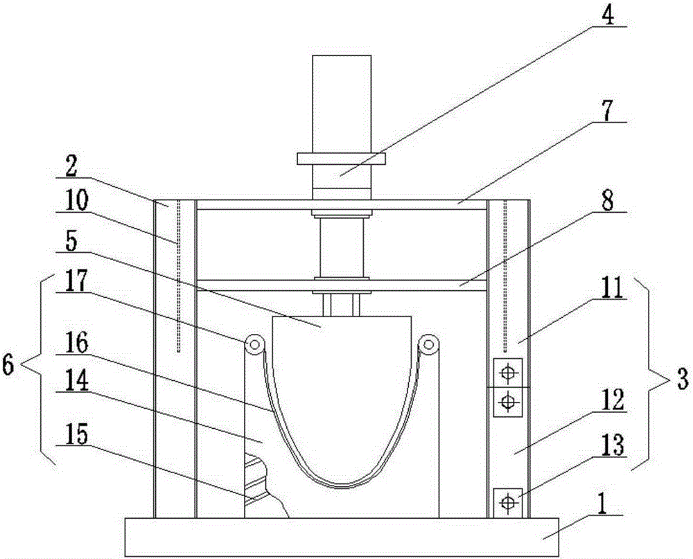
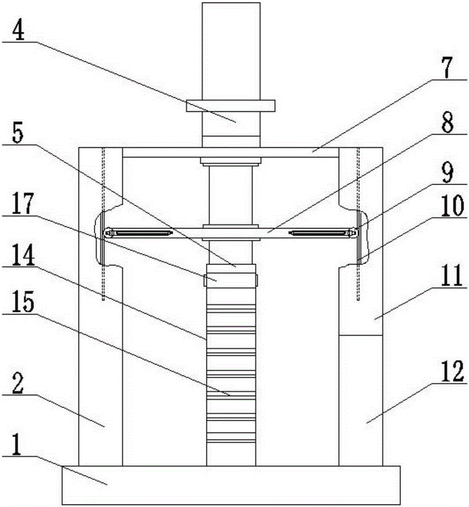
[0026] Such as Figures 1 to 3 As shown, a wind power generation tower door frame forming and flange correction device, which includes a base 1, a fixed column 2, a movable column 3, a hydraulic cylinder 4, an upper mold 5, a lower mold 6, a fixed plate 7 and a balance plate 8, Two fixed columns 2 are arranged side by side on one side of the base 1, two movable columns 3 are arranged side by side on the other side of the base 1, the fixed plate 7 is arranged above the fixed column 2 and the movable column 3, and fixed with the fixed column 2 and the movable column 3 connection, four pulleys 9 are arranged on the balance platen 8, vertical slide rails 10 are arranged on the fixed column 2 and the movable column 3, and the pulleys 9 are buckled on the slide rails 10, and the cylinder body of the hydraulic cylinder 4 is connected with the fixed column The plate 7 is fixedly connected, the piston rod of the hydraulic cylinder 4 is fixedly connected with the balance platen 8, the u...

Embodiment 2

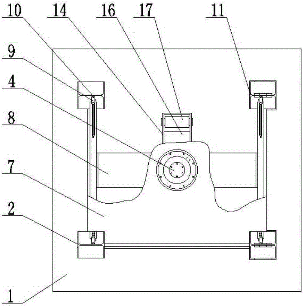
[0029] Such as Figure 4 As shown, a wind power generation tower door frame forming and flange correction device, which includes a base 1, a fixed column 2, a movable column 3, a hydraulic cylinder 4, an upper mold 5, a lower mold 6, a fixed plate 7 and a balance plate 8, Two fixed columns 2 are arranged side by side on one side of the base 1, two movable columns 3 are arranged side by side on the other side of the base 1, the fixed plate 7 is arranged above the fixed column 2 and the movable column 3, and fixed with the fixed column 2 and the movable column 3 connection, four pulleys 9 are arranged on the balance platen 8, vertical slide rails 10 are arranged on the fixed column 2 and the movable column 3, and the pulleys 9 are buckled on the slide rails 10, and the cylinder body of the hydraulic cylinder 4 is connected with the fixed column The plate 7 is fixedly connected, the piston rod of the hydraulic cylinder 4 is fixedly connected with the balance platen 8, the upper d...


PUM


Abstract

The invention discloses a wind power tower door frame forming and flange correcting device. The device comprises a base, fixed upright columns, movable upright columns, a hydraulic cylinder, an upper die, a lower die, a fixed plate and a balance pressing plate. The two fixed upright columns are arranged on one side of the base side by side. The two movable upright columns are arranged on the other side of the base side by side. The fixed plate is fixed on the fixed upright columns and the movable upright columns, and fixedly connected with the fixed upright columns and the movable upright columns. The balance pressing plate is provided with four sliding wheels. The fixed upright columns and the movable upright columns are provided with vertical sliding rails, the sliding wheels are buckled to the sliding rails, a cylinder body of the hydraulic cylinder is fixedly connected with the fixed plate, a piston rod of the hydraulic cylinder is fixedly connected with the balance pressing plate, the upper die is connected to the bottom end of the piston rod of the hydraulic cylinder, the lower die is arranged on the base, and the upper die is matched with the lower die. The wind power tower door frame forming and flange correcting device is safe, reliable, convenient to operate and capable of improving production efficiency and guaranteeing product quality.

Description

technical field [0001] The invention relates to a processing device for parts of wind power generation equipment, in particular to a device for forming a door frame of a wind power generation tower and correcting flanges. Background technique [0002] As a clean and renewable energy, wind energy has been paid more and more attention by countries all over the world. It has a huge potential. The country attaches great importance to the new energy strategy, and the wind power industry is rising rapidly in our country. [0003] With the development of the wind power industry and fierce market competition, it has become an inevitable trend to manufacture wind power towers with high quality and high efficiency. The door frame in the wind power tower must not only be of good quality, but also beautiful. Usually, the door frame is cut by numerical control, bent and formed by two steel plates, and welded together. It is difficult to achieve the designed bending effect during the for...

Claims


Application Information

Patent Timeline
IPC IPC(8): B21D35/00B21D1/00B21D22/02
Inventor 裘学强朱锴年李一峰管伟周晓辉魏霏霏缪飞燕
Owner SINOHYDRO BUREAU 4 JIUQUAN NEW ENERGY EQUIPCO
Why Eureka
Try Eureka