A multifunctional aluminum cladding cleaning machine

A cleaning machine and multi-functional technology, applied in the direction of mechanical cleaning, manufacturing tools, metal processing equipment, etc., can solve the problems of high labor intensity, low production efficiency, high cost of tool replacement, etc., to reduce the labor intensity of workers, reduce The effect of maintenance cost and production cost saving

Active Publication Date: 2017-05-17
NFC (SHENYANG) METALLURGICAL MACHINERY CO LTD
View PDF7 Cites 0 Cited by
  • Summary
  • Abstract
  • Description
  • Claims
  • Application Information

AI Technical Summary

Problems solved by technology

[0003] The patent number is 200810011087.7, and the name is the invention patent of "A Tilting Type Aluminum Ladle Cleaning Machine". It discloses a tilting aluminum ladle cleaning machine. During the long-term use of the aluminum ladle cleaning machine, the following problems occurred : 1. The function of the aluminum ladle cleaning machine is only to clean the residue in the aluminum ladle, and it cannot clean the aluminum suction tube. It has few functions and cannot meet the needs of modern production.
[0004] 2. Since the aluminum cladding beam is set on the side of the aluminum cladding, when the aluminum cladding is placed on the tipping device, the aluminum cladding beam is located directly above the aluminum cladding, and the aluminum cladding cannot be tipped at this time; the aluminum cladding can only be manually lifted. Only when the package beam is rotated to the side of the aluminum package can the aluminum package be tipped over, which is inconvenient to use and low in production efficiency
[0005] 3. The structure of the cutting tool is relatively complicated, usually welded connection, the structure is complex, and because the tool generates a lot of heat during operation, the weld is easily damaged; the tool life is low, and the cost of tool replacement is high
[0006] 4. The residue trolley is lifted by the crane and manually turned over to dump the residue. The labor intensity of the staff is high, and there are potential safety hazards

Method used


Image

  • A multifunctional aluminum cladding cleaning machine
  • A multifunctional aluminum cladding cleaning machine
  • A multifunctional aluminum cladding cleaning machine

Examples


Embodiment Construction

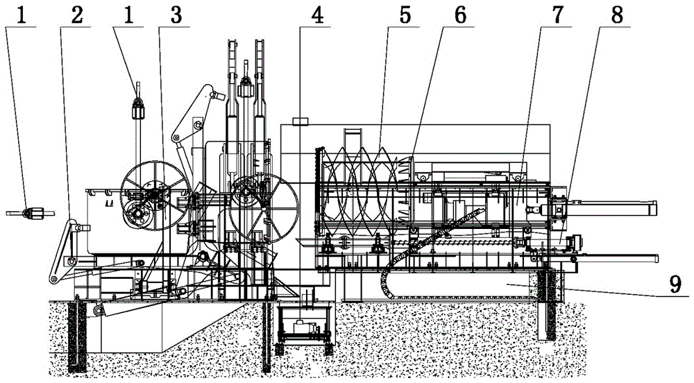
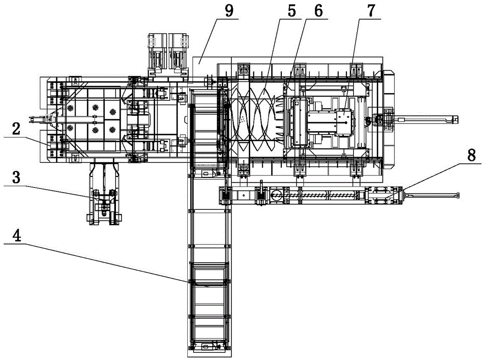
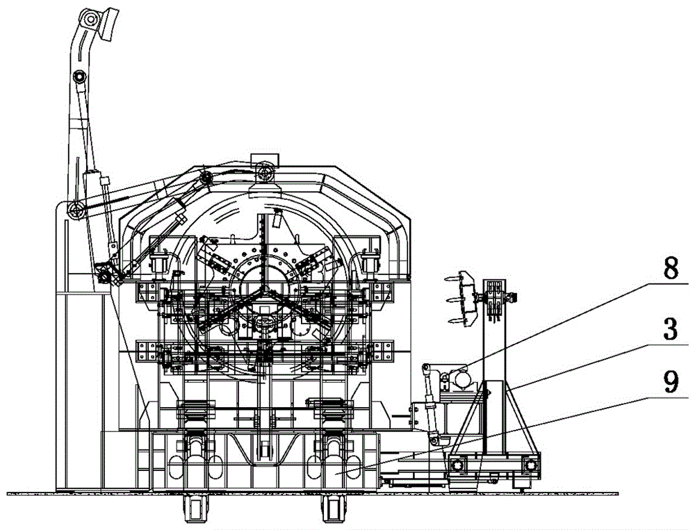
[0028] The present invention comprises a machine base 9, a driving device 7 is arranged on the top of the machine base 9, a cutter head 6 with an aluminum bag cleaning tool 5 is arranged on the driving device 7, and a tilting device 2 is arranged on the machine base 9 corresponding to the aluminum bag cleaning tool 5 The bottom of the machine base 9 is corresponding to the residue car 4 between the aluminum bag cleaning tool 5 and the tipping device 2, and it is characterized in that: the machine base 9 is located on the side of the driving device 7 and the aluminum bag cleaning tool 5. Aluminum suction tube cleaning machine 8; the cutter head 6 is provided with a knife rest 13, and the aluminum bag cleaning cutter 5 is fixedly connected with the knife rest 13 through bolts 14.

[0029] The surface of the cutter head 6 is provided with a groove, the groove is provided with an L-shaped knife seat 11, the L-shaped knife seat 11 is provided with an L-shaped knife rest 13, and the ...


PUM


Abstract

A multifunctional aluminum ladle cleaning machine relates to an improvement of the structure of the aluminum ladle cleaning machine. The invention provides a multifunctional aluminum ladle cleaning machine with multiple functions, convenient use and improved production efficiency. The invention comprises a machine base, a driving device is arranged on the top of the machine base, a cutter head with an aluminum bag cleaning tool is arranged on the driving device, a tipping device is arranged on the machine base corresponding to the aluminum bag cleaning tool, and the bottom of the machine base is corresponding to the aluminum bag cleaning tool. A residue car is arranged between the tool and the tipping device, and it is characterized in that: an aluminum suction tube cleaning machine is arranged on the side of the drive device and the aluminum bag cleaning tool on the base; a tool holder is provided on the cutter head, The aluminum bag cleaning tool is fixedly connected with the tool holder through bolts.

Description

technical field [0001] The invention relates to an improvement of the structure of an aluminum cladding cleaning machine. Background technique [0002] The multi-functional aluminum ladle cleaning machine is installed in the ingot casting workshop of the electrolytic aluminum plant to remove aluminum slag and sediment in the aluminum ladle and aluminum tube, realize the mechanization of aluminum ladle cleaning, reduce labor intensity, improve the working environment, and increase production efficiency. [0003] The patent number is 200810011087.7, and the name is the invention patent of "A Tilting Type Aluminum Ladle Cleaning Machine". It discloses a tilting aluminum ladle cleaning machine. During the long-term use of the aluminum ladle cleaning machine, the following problems occurred : 1. The function of this aluminum ladle cleaning machine is only for the cleaning of the residue in the aluminum ladle cleaning, and it cannot clean the aluminum suction pipe. It has few func...

Claims


Application Information

Patent Timeline
Patent Type & Authority Patents(China)
IPC IPC(8): B22D43/00
Inventor 高春兰李福俊李东福刘久新常兴娥张晓峰赵俊李玲玲
Owner NFC (SHENYANG) METALLURGICAL MACHINERY CO LTD
Why Eureka
Try Eureka