Double chip safety soldering fixture with induction detection

A welding fixture and induction detection technology, applied in the field of double-chip welding fixtures, can solve problems such as low welding efficiency and difficulty in controlling welding quality, and achieve the effects of ensuring safe welding, reducing costs, and high-quality welding

Active Publication Date: 2017-12-08
优盛思实业沭阳有限公司
View PDF5 Cites 0 Cited by
  • Summary
  • Abstract
  • Description
  • Claims
  • Application Information

AI Technical Summary

Problems solved by technology

At present, due to the lack of special welding fixtures, the three parts can only be welded separately by hand. The welding efficiency is low and the welding quality is difficult to control.

Method used


Image

  • Double chip safety soldering fixture with induction detection
  • Double chip safety soldering fixture with induction detection
  • Double chip safety soldering fixture with induction detection

Examples


Embodiment Construction

[0021] The specific embodiments of the present invention will be further described below in conjunction with the accompanying drawings.

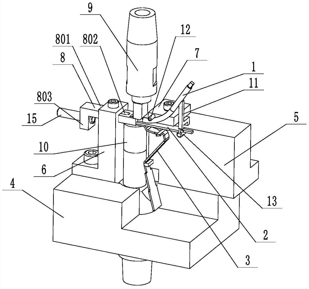
[0022] like Figure 5 As shown, the dual-chip safety welding fixture with induction detection in this embodiment is used for welding between the double-chip 2, the copper wire 1 and the support plate 3, the copper wire 1 is curved, and its welding end is a square tube end 101, the support plate 3 is a multi-bending structure, which has an upper horizontal plate welding end 301, a middle middle bending part 302 and a lower lower bending part 303, the middle bending part 302 and the lower bending part 303 The direction of deflection is opposite.

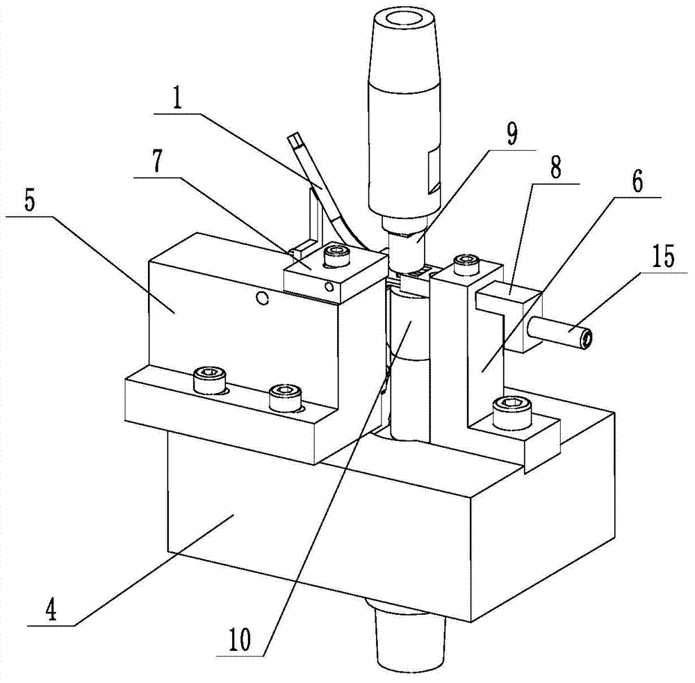
[0023] like figure 1 , figure 2 As shown, the welding jig includes a welding seat 4, the center of the welding seat 4 is equipped with a lower fixed electrode 10, and an upper movable electrode 9 is arranged above the lower fixed electrode 10, and is installed on the welding seat 4 on both sides ...


PUM


Abstract

The invention relates to an induction detecting bimorph safe welding fixture. The induction detecting bimorph safe welding fixture comprises a welding seat, wherein a lower fixed electrode is mounted in the center of the welding seat; an upper movable electrode is arranged above the lower fixed electrode; a first fixing seat and a second fixing seat are mounted on the welding seat and positioned on the two sides of the lower fixed electrode; a positioning block and a positioning rack are mounted on the upper end surface of the first fixing seat; an upper bumping post is mounted on the side surface of the positioning block; a lower bumping post positioned below the upper bumping post in a staggered manner is mounted on the side surface of the first fixing seat; a bimorph is mounted between the upper bumping post and the lower bumping post; the square tube end of a copper wire is mounted between the bimorph and the upper bumping post, and the other end of the copper wire is propped against the upper end of the positioning rack; a positioning post for limiting a supporting plate is also arranged on the side surface of the first fixing seat; the horizontal plate welding end of the supporting plate is buckled between the bimorph and the lower fixed electrode; an end part limiting rack is mounted on the second fixing seat; the end part of the end part limiting rack is arranged on the upper end surface of the lower fixed electrode, and is propped against the end surfaces of the bimorph, the horizontal plate welding end and the square tube end.

Description

technical field [0001] The invention relates to the field of welding technology, in particular to a welding jig for double wafers. Background technique [0002] like Figure 5 As shown, the workpieces to be welded include a double chip 2, a copper wire 1 and a support plate 3, the copper wire 1 is curved, and its welding end is a square pipe end 101, and the support plate 3 is a multi-bend structure with an upper horizontal The welding end 301 of the plate, the middle bending part 302 in the middle and the lower bending part 303 in the lower part, the bending directions of the middle bending part 302 and the lower bending part 303 are opposite. At present, due to the lack of special welding fixtures, the three parts can only be welded separately by hand. The welding efficiency is low and the welding quality is difficult to control. Contents of the invention [0003] Aiming at the above-mentioned shortcomings of the prior art, the applicant conducts research and design, an...

Claims


Application Information

Patent Timeline
Patent Type & Authority Patents(China)
IPC IPC(8): B23K11/36B23K37/04
CPCB23K11/36B23K37/0443
Inventor 王波
Owner 优盛思实业沭阳有限公司
Why Eureka
Try Eureka