Eureka AIR delivers breakthrough ideas for toughest innovation challenges, trusted by R&D personnel around the world.

Drawer type chip removing water tank

A drawer type, water tank technology, applied in metal processing machinery parts, maintenance and safety accessories, metal processing equipment, etc., can solve the problems affecting the precision of workpiece processing, and achieve the effect of convenient operation, labor saving and simple structure

Inactive Publication Date: 2015-12-30
FOSHAN PRATIC CNC SCI & TECH
View PDF6 Cites 4 Cited by
  • Summary
  • Abstract
  • Description
  • Claims
  • Application Information

AI Technical Summary

Problems solved by technology

[0003] Although the coolant solves the above-mentioned cooling, lubrication, cleaning and rust prevention problems, the processing machine tool will accumulate a large amount of cooling water and residual waste during the working process. If the drainage and chip removal are not smooth, it will accumulate on the surface of the workpiece or the transmission The position of the mechanism will seriously affect the accuracy of the workpiece processing

Method used


Image

  • Drawer type chip removing water tank
  • Drawer type chip removing water tank
  • Drawer type chip removing water tank

Examples


Embodiment Construction

[0023] The technical solutions of the present invention will be further described below in conjunction with the accompanying drawings and through specific implementation methods.

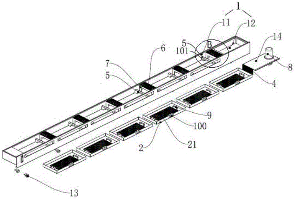
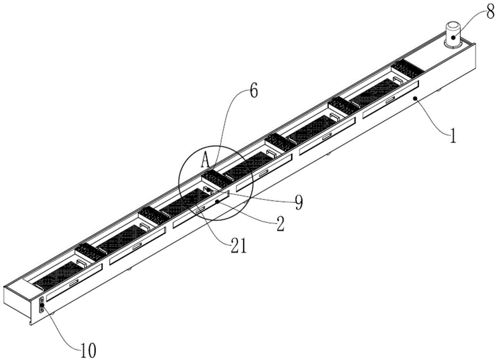
[0024] like figure 1 and figure 2 A drawer-type chip removal water tank is shown, including a box body 1 and a plurality of chip trays 2;

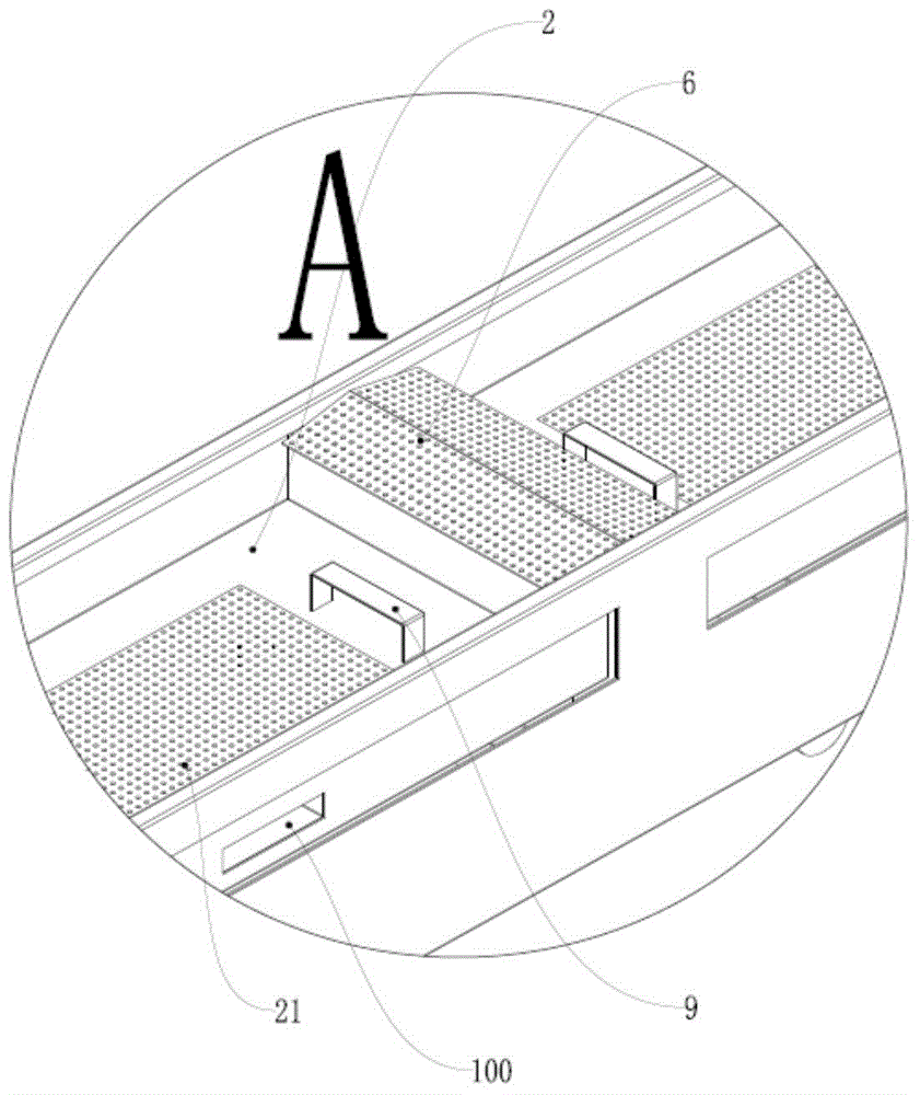
[0025] Described box body 1 is provided with filter net plate 4, and described filter net plate 4 is placed vertically, and described box body 1 is divided into guide dust case lattice 11 and filter case lattice 12; One of described dust guide case lattice 11 The side is provided with a plurality of chip receiving trays 2 that match the chip receiving tray 3; the inside of the chip guide box 11 is provided with a support frame 5, and the support frame 5 is an inverted U-shaped structure 5; The upper end of the support frame 5 is inclined toward the direction of the chip receiving tray 2; the chip receiving tray 2 is inserted into the chip guide box 11 through...


PUM


Abstract

A drawer type chip removing water tank comprises a tank body and a plurality of chip collecting discs. Filter screen plates are arranged in the tank body and are vertically placed, and the tank body is divided into chip guide tank boxes and filter tank boxes. Chip collecting disc openings matched with the chip collecting discs are formed in one side faces of the chip guide tank boxes. Supporting frames are arranged in the chip guide tank boxes, and are of an inverted-U-shaped structure. The upper ends of the supporting frames are inclined towards the chip collecting discs. The chip collecting discs are inserted into the chip guide tank boxes through the chip collecting disc openings, and supported by the supporting frames, and clearances are formed between the chip collecting discs and the bottoms of the chip guide tank boxes. Water pumps are mounted in the filter tank boxes, and screen meshes are arranged at the bottoms of the chip collecting discs. The drawer type chip collecting discs are arranged in the tank body, so that waste chips are effectively removed, cooling liquid can be repeatedly utilized, the structure is simple, operation is convenient, and labor is saved.

Description

technical field [0001] The invention relates to the technical field of chip removal in numerical control machining, in particular to a drawer-type chip removal water tank. Background technique [0002] During the actual cutting process of the machine tool (especially when processing aluminum), similar problems (sticking knife, broken milling cutter, broken tap, rotten teeth, etc.) often occur. Except for the factors of the tool and the machine tool, the coolant Played a big role in the whole processing process. The coolant takes away a large amount of heat energy generated during cutting, reduces the temperature of the workpiece, and reduces the thermal deformation of the workpiece. Controls the generation of residual stress and microscopic cracks; during cutting, the tool and the workpiece are actually a process of extrusion and friction. The coolant inside acts as a lubricant, which reduces the frictional resistance (a lubricating film is formed between the tool and the w...

Claims


Application Information

Patent Timeline
Patent Type & Authority Applications(China)
IPC IPC(8): B23Q11/00B23Q11/10
CPCB23Q11/0042B23Q11/10Y02P70/10
Inventor 刘世泉刘杜军
Owner FOSHAN PRATIC CNC SCI & TECH
Why Eureka
Eureka Blog
Learn More