Gas inflowing and cooling device for MOCVD equipment

A cooling device and equipment technology, applied in gaseous chemical plating, metal material coating process, coating and other directions, can solve the problems of complex structure of air intake device, affecting product quality, disturbing parasitic particles, etc., to ensure the quality of film growth , Improve the film growth rate and inhibit the effect of parasitic particles

Active Publication Date: 2015-12-30
ADVANCED MICRO FAB EQUIP INC CHINA
View PDF8 Cites 9 Cited by
  • Summary
  • Abstract
  • Description
  • Claims
  • Application Information

AI Technical Summary

Problems solved by technology

[0004] like figure 1 , figure 2 , image 3 As shown, the above-mentioned air intake device has the following disadvantages: at the edge of the air intake device, different gas mixing states and gas flow rates are present at different positions on the circumference, which is easy to form a vortex; The distribution area of ​​the reaction source gas is alternately distributed strip type, non-centrosymmetric, which makes the distribution of the two reaction source gases uneven on different substrates or on different positions of the same substrate, especially between the central area and the edge area. Inhomogeneous film formed by the final deposition, affecting product quality
[0006] However, taking the above-mentioned first embodiment as an example, the air intake device is not only complex in structure, but also has a flat bottom surface, and there are many areas on this plane where no gas flows through, and it is easy to form eddy currents to disturb parasitic particles, causing parasitic particles Clings to the underside of the air intake and is difficult to remove
Moreover, the outlet on the lower surface of the third gas diffusion chamber is far away from the output positions of the two reaction source gases, so it is difficult for the purge gas delivered through the outlet to separate the two reaction source gases or remove the attached parasitic particles

Method used


Image

  • Gas inflowing and cooling device for MOCVD equipment
  • Gas inflowing and cooling device for MOCVD equipment
  • Gas inflowing and cooling device for MOCVD equipment

Examples


Embodiment Construction

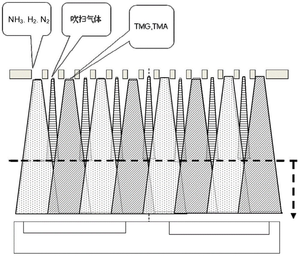
[0050] Such as Figure 4 As shown, the air inlet device provided by the present invention is a shower head 800, which is arranged on the top of the MOCVD (metal organic chemical vapor deposition) equipment reaction chamber 900, through the first air inlet conduit 810 provided, the second inlet The gas conduit 820 and the first air inlet 830 respectively deliver the organometallic gas and the hydride gas into the reaction chamber 900, and the carrier gas that carries them to the surface of the substrate 920 for film deposition reaction, and at the same time passes through the first The carrier gas delivered by the gas inlet 830 separates the organometallic gas and the hydride gas from each other, so as to prevent the premature reaction of the just injected organometallic gas and hydride gas from generating parasitic gas near the gas inlet on the bottom surface of the shower head 800. particles.

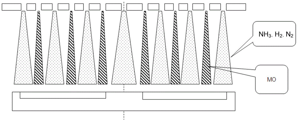
[0051] Such as Figure 5 As shown, a group of second air inlets 840 is also prov...


PUM


Abstract

The invention discloses a gas inflowing and cooling device for MOCVD equipment. The gas inflowing and cooling device is provided with spray heads located at the top of the interior of a reaction chamber, gas inflowing guide pipes for organic metal gas are arranged in gas inlets for isolation gas in a penetrating mode, the isolation gas can form curtain-shaped gas flow and surround the periphery of the organic metal gas, and therefore the organic metal gas which is sprayed just now and hydride gas can be isolated and prevented from untimely reacting to generate parasitic particles. In addition, the parasitic particles can be prevented from being formed nearby the gas inlets formed in the bottom face of the gas inflowing device, therefore, the conveyed organic metal gas and the hydride gas can be evenly distributed on a base and all substrates, the thin film growth quality is guaranteed, and the thin film growth rate is improved.

Description

technical field [0001] The invention relates to semiconductor manufacturing equipment, in particular to an air intake and cooling device for MOCVD equipment. Background technique [0002] At present, in the metal-organic chemical vapor deposition method (hereinafter referred to as MOCVD), the gas of II or III metal-organic compounds and the hydride gas containing IV or V elements are introduced into the reaction chamber of the MOCVD equipment, so that the mixture of the two When the gas is sent to the surface of the substrate placed on the bottom base in the reaction chamber, a thermal decomposition reaction can occur on the surface of the substrate, thereby epitaxially growing to form a compound single crystal film. [0003] Such as figure 1 , figure 2 As shown, in a gas inlet device provided by US2010 / 0143588A1, a gas distribution plate located at the top of the reaction chamber is provided, which includes a plurality of elongated tubular gas distribution elements exten...

Claims


Application Information

Patent Timeline
Patent Type & Authority Applications(China)
IPC IPC(8): C23C16/455C23C16/44
Inventor 泷口治久
Owner ADVANCED MICRO FAB EQUIP INC CHINA
Why Eureka
Try Eureka