Steam turbine circulation part cleaning system and cleaning method

A cleaning system and steam turbine technology, applied to mechanical equipment, engine components, machines/engines, etc., can solve the problems of long cleaning cycle, low efficiency, high cleaning cost, etc., and achieve the effect of short cleaning cycle, improved safety and simple operation

Inactive Publication Date: 2015-12-30
苏州市江远热电有限责任公司
View PDF2 Cites 4 Cited by
  • Summary
  • Abstract
  • Description
  • Claims
  • Application Information

AI Technical Summary

Problems solved by technology

At the same time, due to the large amount of boiler desuperheating water (about 3-4t / h) and the use of mixed water spray cooling, the steam with sodium ions enters the steam turbine. The increase of salt increases the pressure of the monitoring section, which reduces the efficiency and economy of the unit, and also poses a certain threat to safe operation
[0004] The flow part is prone to sodium compound salt scaling, which causes problems such as pressure rise and efficiency drop in the monitoring section. The scaling of the flow part of the steam turbine must be cleaned regularly to avoid the above problems. The current cleaning methods mainly include sandblasting and high pressure. Water flushing, manual polishing, etc. must be carried out in the state of unit overhaul and cylinder removal. The unit overhaul period generally takes 3 to 4 years. The cleaning period is longer and the cleaning cost is higher.

Method used


Image

  • Steam turbine circulation part cleaning system and cleaning method
  • Steam turbine circulation part cleaning system and cleaning method

Examples


Embodiment Construction

[0012] The present invention will be further described below in conjunction with the accompanying drawings and specific embodiments.

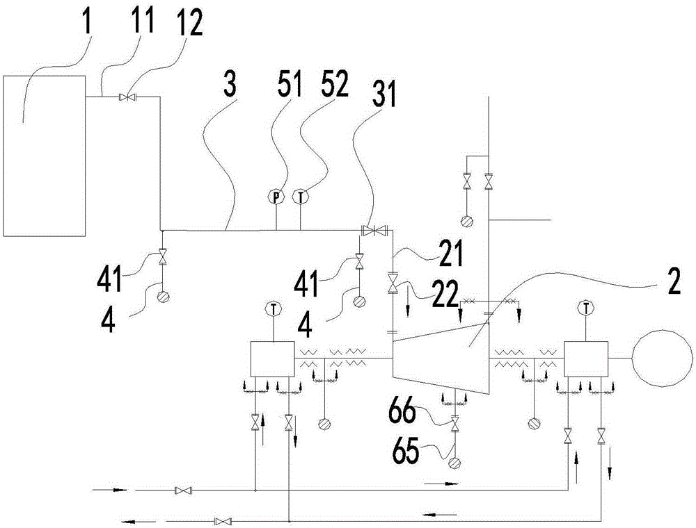
[0013] Such as figure 1 As shown, the steam turbine circulation part cleaning method includes a steam turbine 2 and a boiler 1, the boiler 1 is provided with a boiler outlet pipe 11, the boiler outlet pipe 11 is provided with a boiler outlet valve 12, and the steam turbine 2 is provided with a steam turbine inlet pipe 21. The steam turbine inlet pipe 21 is provided with a steam turbine inlet valve 22, the boiler outlet pipe 11 and the steam turbine inlet pipe 21 are connected through the steam main pipe 3, and the steam main pipe 3 is provided with a main valve 31, a steam outlet pressure gauge 32 and an outlet valve. The steam temperature gauge 33, the outlet steam pressure gauge 32 and the outlet steam temperature gauge 33 are all located upstream of the main valve 31, and the steam main pipe 3 is also provided with a plurality of water deliv...


PUM


Abstract

The invention discloses a steam turbine circulation part cleaning system and cleaning method. The steam turbine circulation part cleaning system comprises a steam turbine and a steam generator, wherein a generator steam outlet pipe is arranged on the steam generator; a generator steam outlet valve is arranged on the generator steam outlet pipe; a steam turbine steam inlet pipe is arranged on the steam turbine; a steam turbine steam inlet valve is arranged on the steam turbine steam inlet pipe; the generator steam outlet pipe and the steam turbine steam inlet pipe are connected through a steam main pipe; a main valve, an outlet steam pressure gauge and an outlet steam temperature gauge are arranged on the steam main pipe; both the outlet steam pressure gauge and the outlet steam temperature gauge are located at the upstream part of the main valve; a plurality of drain pipes are arranged on the steam main pipe, and drain valves are arranged on the drain pipes respectively; during cleaning of a steam turbine circulation part, the main valve is opened when the steam pressure of the steam generator reaches 3.0 MPa and the steam temperature reaches 235 DEG C, steam impulses the steam turbine to start, and flowing steam washes out scales on an impeller, blades, a partition and a spray nozzle group of the steam turbine.

Description

technical field [0001] The invention relates to the field of steam turbine maintenance in a small thermal power plant, in particular to a steam turbine circulation part cleaning system and a cleaning method which can effectively clean the steam turbine circulation part. Background technique [0002] When a small steam turbine in a thermal power plant is running, under the same operating conditions (same flow rate), the steam consumption, pressure in the monitoring section, and exhaust temperature all increase, especially the pressure in the monitoring section gradually increases to 2.3MPa (0.12 MPa higher than the manufacturer's specification) MPa), and the electric load decreased by about 1000kW. According to the analysis of relevant data and combined with the inspection and overhaul of the unit, it was found that it was caused by salt accumulation in the flow part of the steam turbine. During the inspection and overhaul of the unit, it was found that there were various deg...

Claims


Application Information

Patent Timeline
Patent Type & Authority Applications(China)
IPC IPC(8): F01D25/00
Inventor 孙灵邵泽成龙利华陆建新
Owner 苏州市江远热电有限责任公司
Why Eureka
Try Eureka