Rotary compressor

A technology of a rotary compressor and a compression mechanism, which is applied in the field of compressors, can solve the problems of reduced compressor performance, poor reliability, and increased centrifugal force during rotor operation, so as to reduce the possibility of elastic deformation, improve performance and The effect of improving reliability and assembly accuracy

Active Publication Date: 2015-12-30
GUANGDONG MEIZHI COMPRESSOR +1
View PDF6 Cites 4 Cited by
  • Summary
  • Abstract
  • Description
  • Claims
  • Application Information

AI Technical Summary

Problems solved by technology

The ensuing problem is that due to the unbalanced electromagnetic tension in the motor gap, the crankshaft of the compressor is elastically deformed at the moment of starting, causing the rotor to collide with the inner diameter of the stator.
At the same time, the increase of the motor speed increases the centrifugal force of the rotor, and the end of the rotor and the inner diameter of the stator often scrape and collide, and the swing of the crankshaft will increase the wear between the crankshaft and the compression assembly, which will eventually increase the noise

Method used


Image

  • Rotary compressor
  • Rotary compressor
  • Rotary compressor

Examples


Example Embodiment

[0037] The embodiments of the present invention will be described in detail below. Examples of the embodiments are shown in the accompanying drawings, wherein the same or similar reference numerals indicate the same or similar elements or elements with the same or similar functions. The embodiments described below with reference to the accompanying drawings are exemplary, and are intended to explain the present invention, but should not be construed as limiting the present invention.

[0038] The following disclosure provides many different embodiments or examples for implementing different structures of the present invention. In order to simplify the disclosure of the present invention, the components and settings of specific examples are described below. Of course, they are only examples, and are not intended to limit the invention. In addition, the present invention may repeat reference numbers and / or letters in different examples. This repetition is for the purpose of simpl...


PUM


Abstract

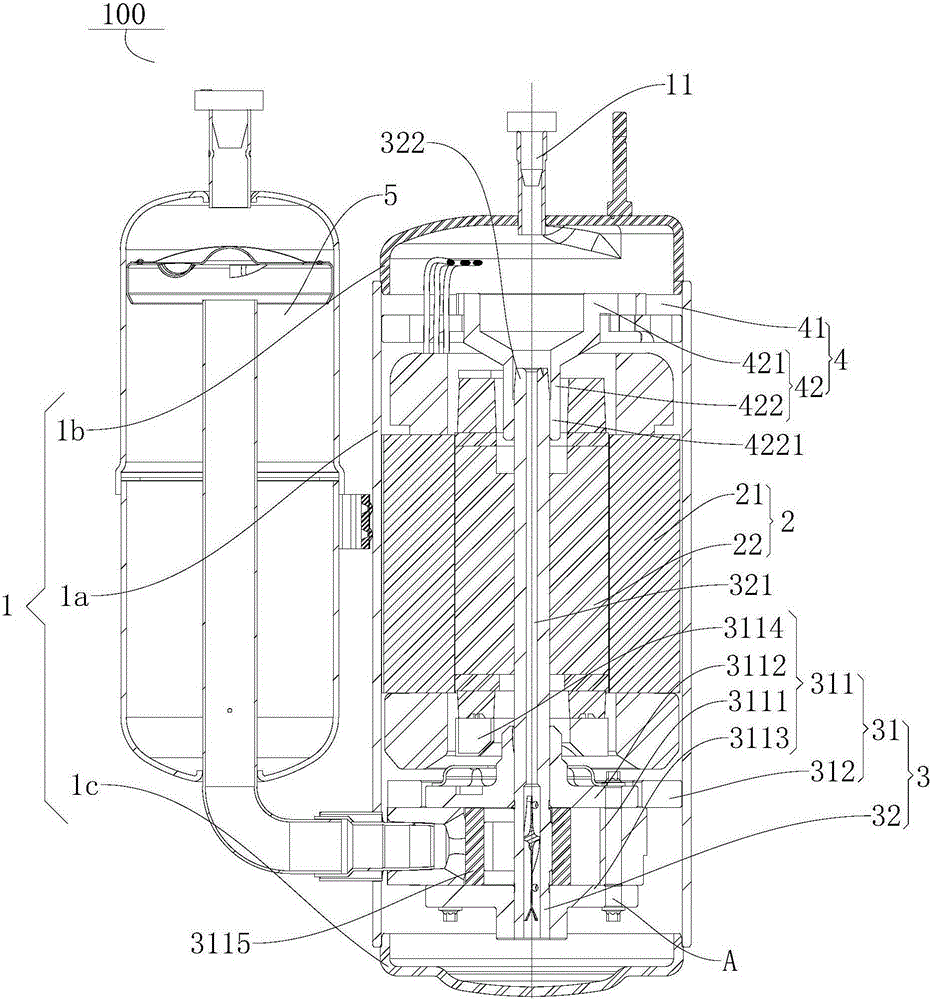
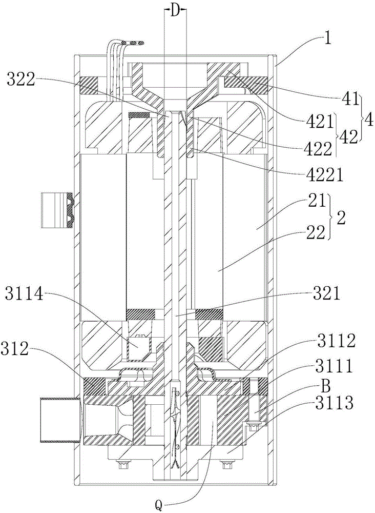
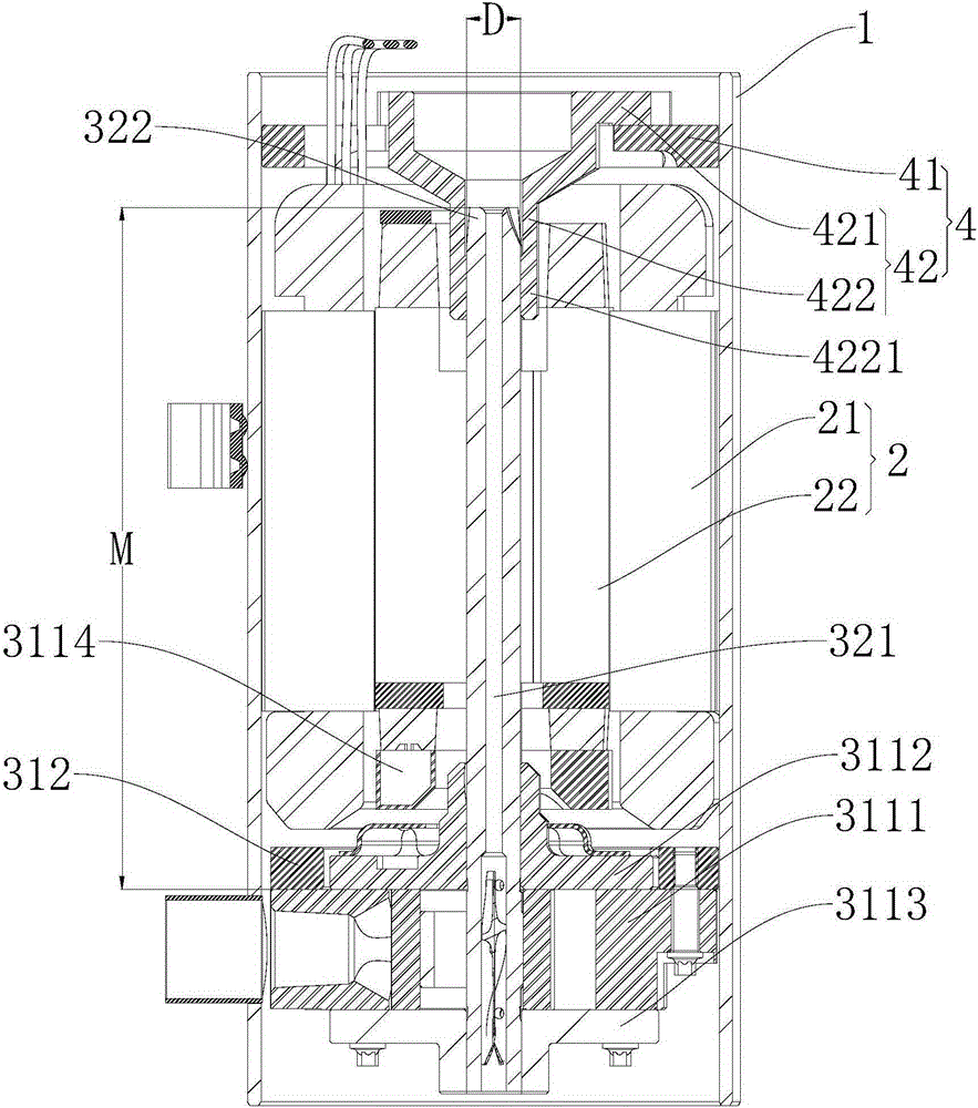
The invention discloses a rotary compressor which comprises a housing, a driving motor, a compressing mechanism and a supporting component. The driving motor is arranged inside the housing and comprises a stator and a rotor which is rotatablely arranged inside the stator. The compressing mechanism is disposed inside the housing and contains a compression component and a crankshaft. The compression component is fixed on the housing and at least comprises an air cylinder component. The supporting component is arranged inside the housing and is positioned at one side of the driving motor, far from the compression component. The supporting component is fixed on the housing and is in supporting fit with one end of the crankshaft that passes through the rotor. The rotary compressor is configured under the following condition: Q/D is less than or equal to 22 cm<2> and greater than or equal to 10 cm<2>, wherein Q is displacement of the rotary compressor, and D is shaft diameter of a main shaft section of the crankshaft positioned at one side of the air cylinder component near the driving motor. According to the rotary compressor, assembly accuracy is raised, and collision between rotor and stator bore is reduced as well as abrasion between the crankshaft and the compression component. Thereby, performance and reliability of the compressor are enhanced.

Description

technical field [0001] The invention relates to the field of compressors, in particular to a rotary compressor. Background technique [0002] With the development of compressor technology and the improvement of high efficiency requirements, the height of the rotary compressor motor is gradually increased, the motor speed is getting higher and higher, the diameter of the crankshaft is getting smaller and smaller, the ratio of length to diameter is getting bigger, and the rigidity of the crankshaft is getting higher and higher. The worse it is, the ability to resist deformation is gradually reduced. The ensuing problem is that due to the unbalanced electromagnetic tension in the motor gap, the crankshaft of the compressor is elastically deformed at the moment of starting, causing the rotor to collide with the inner diameter of the stator. At the same time, the increase of the motor speed will increase the centrifugal force of the rotor, and the end of the rotor will often scr...

Claims


Application Information

Patent Timeline
IPC IPC(8): F04C23/02F04C29/00
Inventor 祝佳利赖化鸿周林林达拉陈振华
Owner GUANGDONG MEIZHI COMPRESSOR
Why Eureka
Try Eureka