Pneumatic sensor

A pneumatic sensor and air flow technology, applied in the field of sensors, can solve the problems of false triggering, poor sensitivity and stability, complicated manufacturing process, etc., and achieve the effect of simplifying the manufacturing process, improving the driving force, and increasing the vibration frequency

Active Publication Date: 2015-12-30
NAZHIYUAN TECH TANGSHAN LLC
View PDF8 Cites 3 Cited by
  • Summary
  • Abstract
  • Description
  • Claims
  • Application Information

AI Technical Summary

Problems solved by technology

However, the existing pneumatic sensors have complex manufacturing processes, poor

Method used


Image

  • Pneumatic sensor
  • Pneumatic sensor
  • Pneumatic sensor

Examples


Embodiment Construction

[0056] In order to fully understand the purpose, features and effects of the present invention, the present invention will be described in detail through the following specific embodiments, but the present invention is not limited thereto.

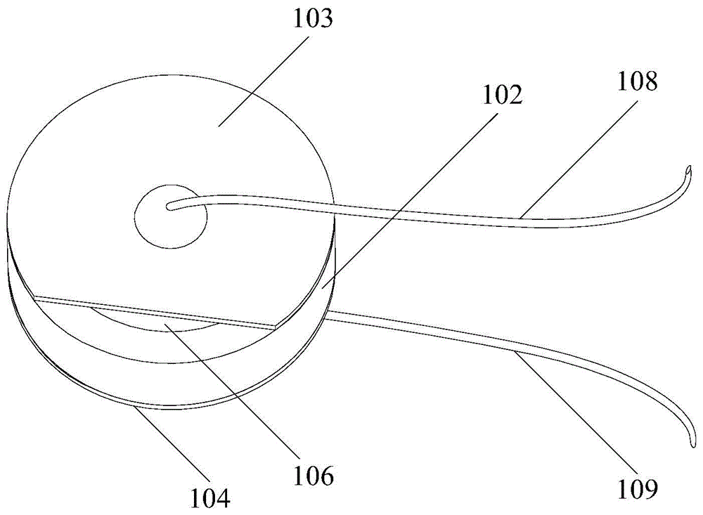
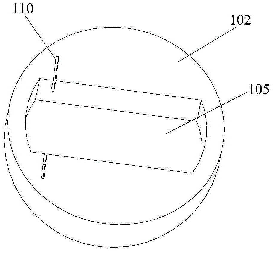
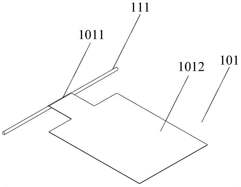
[0057] A pneumatic sensor provided by the present invention has an air inlet and an air outlet, and the pneumatic sensor includes: a first friction component, a casing, a second friction component and a third friction component. Wherein, the housing has a hollow structure with a predetermined shape to form an airflow channel, and the airflow channel communicates with the air inlet and the air outlet, so that air flows into the airflow channel through the air inlet and flows out through the air outlet. The first friction member is arranged in the air flow passage, and the second friction member and the third friction member are arranged at positions capable of contacting the first friction member. When the airflow enters the airflow channel...


PUM


Abstract

The invention discloses a pneumatic sensor which is provided with an air inlet and an air outlet. The pneumatic sensor comprises a first friction component, a shell, a second friction component and a third friction component, wherein the shell is provided with a hollow structure with a preset shape so as to form an air flow channel, and the air flow channel is communicated with the air inlet and the air outlet, thereby enabling an air flow to get into the air flow channel through the air inlet and then flow out through the air outlet; and the first friction component is arranged in the air flow channel, and the second friction component and the third friction component are arranged at positions where the second friction component and the third friction component can be contacted with the first friction component. When the air flow gets into the air flow channel through the air inlet, the first friction component generates friction with the second and/or the third friction component because of an effect of the air flow, and electric signals are generated. The second friction component and the third friction component comprise an electric signal output end of the pneumatic sensor. The pneumatic sensor disclosed by the invention can simplify the manufacturing process of existing pneumatic sensors, a driving force imposed on the first friction component in the pneumatic sensor by the air flow is improved, and thus the sensitivity and the stability of the pneumatic sensor in operation are improved.

Description

technical field [0001] The invention relates to the technical field of sensors, in particular to a pneumatic sensor. Background technique [0002] With the continuous development of technology and people's living needs, people have developed sensors based on various working principles, such as pressure sensors, temperature sensors and pneumatic sensors, etc. These sensors have been applied to all aspects of life and scientific research. For example, pneumatic sensors are applied to electronic cigarettes. [0003] Pneumatic sensors use airflow to make the sensor generate electrical signals. In the prior art, the atomizer, pneumatic sensor and controller in the electronic cigarette are all set in the smoke channel, and the air flow in the smoke channel is driven by the user inhaling at the smoking end, so that the pneumatic sensor senses the airflow signal The trigger controller controls the battery assembly to supply power to the atomizer and atomizes the e-liquid into smok...

Claims


Application Information

Patent Timeline
IPC IPC(8): G01D5/42
Inventor 林同福孙利佳刁海丰钟强赵豪徐传毅
Owner NAZHIYUAN TECH TANGSHAN LLC
Why Eureka
Try Eureka