
An intelligent detection method for high-speed turnout crack damage based on vibration signal fusion

A vibration signal and intelligent detection technology, which is applied in the processing of detection response signals, and the use of sound waves/ultrasonic waves/infrasonic waves to analyze solids, etc., can solve the problems of large data volume, difficult processing, sensor influence, and difficult identification, and achieve suppression of modal mixing. Overlapping problem and the effect of simple signal acquisition and improved accuracy

Inactive Publication Date: 2018-03-13
CHINA RAILWAYS CORPORATION +1
View PDF4 Cites 0 Cited by
  • Summary
  • Abstract
  • Description
  • Claims
  • Application Information

AI Technical Summary

Problems solved by technology

From a technical point of view, the patent application only collects signals from one vibration pickup point for damage detection, and cannot detect the location of the damage (along the direction of the rail line), nor does it know how far the damage is from the vibration pickup point able to detect
Because the track line is too long, to detect the damage position, it is necessary to lay a huge number of sensors along the line and build a sensor network (see paragraph 26 of the patent application specification). The consequences of doing this are: first, the amount of data is too large to handle; After the vibration signal propagates through the rigidity of the rail, it will affect multiple sensors, that is, the damage information will be reflected in the power spectrum characteristics of the vibration signals of multiple sensors, making it difficult to identify damage by the power spectrum feature distinction method
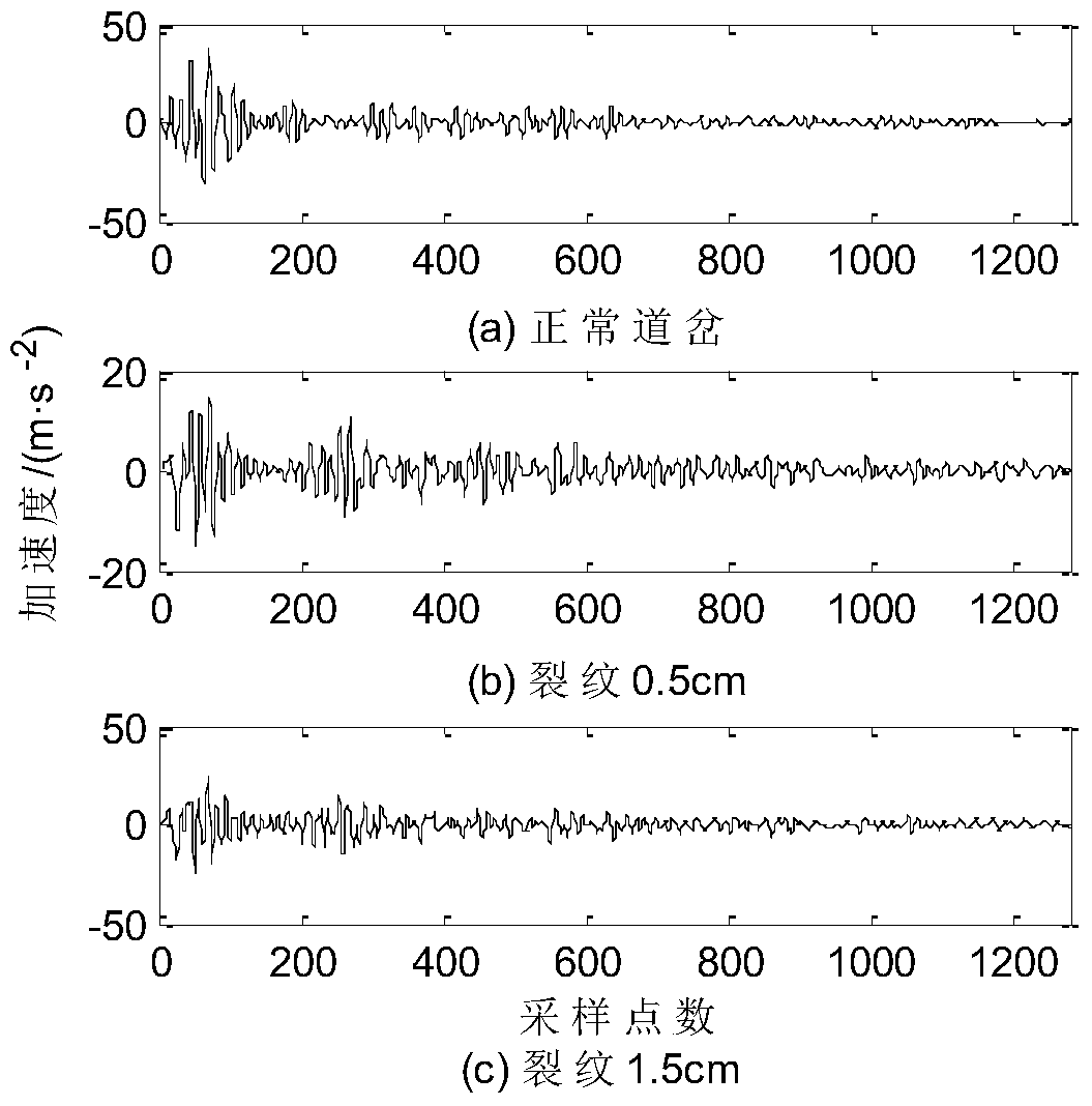
Figure 8 The actual measurement results also verified that the power spectrum feature cannot judge the working status and damage type of the turnout.

Method used


Image

  • An intelligent detection method for high-speed turnout crack damage based on vibration signal fusion
  • An intelligent detection method for high-speed turnout crack damage based on vibration signal fusion
  • An intelligent detection method for high-speed turnout crack damage based on vibration signal fusion

Examples


Embodiment Construction

[0048] The present invention will be described in detail below in conjunction with the accompanying drawings and embodiments.

[0049] Such as figure 1 As shown, the specific embodiment of the present invention is, a kind of high-speed switch crack damage intelligent detection method based on vibration signal, and its steps are:

[0050] (1) According to the change law of the mode shape of the single-span simply supported beam of the turnout, the vibration acceleration sensor is installed at the three measuring points of the tip, middle and tail of the high-speed turnout;

[0051] (2) When the train passes the turnout, the vibration signals of the turnout at the three measuring points are collected respectively. Without loss of generality, the vibration signal at the measuring point of the fork tip is x(i), i=1,...,N, where N is the number of sampling points.

[0052] (3) Adaptively decompose x(i) by using the Complete Ensemble Empirical Mode Decomposition (CEEMD), and obta...


PUM


Abstract

The invention discloses an intelligent detection method for crack damage of a high-speed turnout based on vibration signal fusion. Firstly, vibration acceleration sensors are installed at the tip, center and tail of the high-speed turnout to collect vibration signals, and the vibration signals of the three measuring points are respectively decomposed by CEEMD adaptively to obtain a limited number of IMF components; then the correlation analysis is used to screen out The main IMF component, and calculate the singular entropy eigenvalue of the main IMF component; next, the singular entropy eigenvalues ​​of the vibration signals of multiple measuring points are fused into a feature vector, and the feature vector is input into the LSSVM for training and testing to realize the work of the turnout Judgment of status and damage type. The method of the invention can effectively distinguish different crack damages of the turnout, has good real-time performance and noise resistance, and provides a new technical means for the intelligent diagnosis of the turnout failure.

Description

technical field [0001] The invention relates to an intelligent detection method for crack damage of high-speed turnouts based on vibration signals, and belongs to the technical field of railway turnout detection and maintenance. Background technique [0002] As an important part of the railway track, the turnout is an indispensable line equipment for high-speed railways, and it is also a weak link on the line, which is closely related to the train speed and safety performance. When the train passes through the turnout line, due to the strong impact force of the wheels on the track, it may cause damage types such as contact fatigue, wear, cracks and even track deformation. If the damage of the turnout is not detected and treated in time, as time goes by, the damage of the turnout will further deteriorate, which may cause major accidents such as train derailment, which poses a serious threat to the safe operation of the train. Therefore, it is of great significance to study t...

Claims


Application Information

Patent Timeline
Patent Type & Authority Patents(China)
IPC IPC(8): G01N29/50G01N29/04
Inventor 王小敏陈虹屹郭进潘炜陈建译
Owner CHINA RAILWAYS CORPORATION
Learn More