Energy storage battery detection method

A detection method and technology for energy storage batteries, which are applied in the direction of measuring electricity, measuring devices, measuring electrical variables, etc., can solve the problem of inability to detect the working performance of battery packs

Active Publication Date: 2015-12-30
STATE GRID CORP OF CHINA +3
View PDF3 Cites 12 Cited by
  • Summary
  • Abstract
  • Description
  • Claims
  • Application Information

AI Technical Summary

Problems solved by technology

[0003] The invention aims to solve the problem that the existing battery pack detection technology cannot detect the working performance of the battery pack under actual working conditions, and the invention provides a detection method for an energy storage battery

Method used


Image

  • Energy storage battery detection method
  • Energy storage battery detection method
  • Energy storage battery detection method

Examples


specific Embodiment approach 1

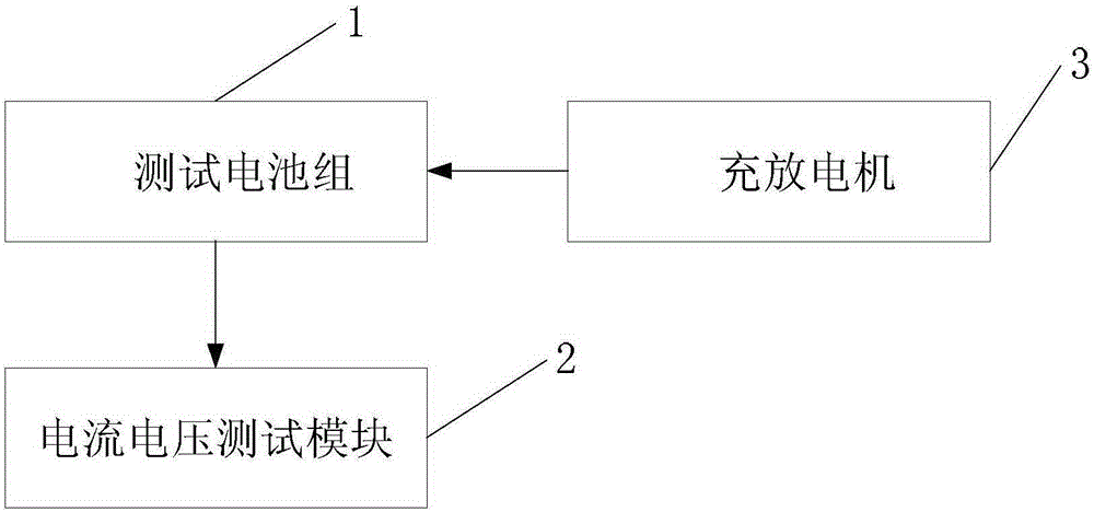
[0053] Specific implementation mode one: see Figure 1 to Figure 3 Describe this embodiment, an energy storage battery detection method described in this embodiment, the method is realized based on the test battery pack 1, the current and voltage test module 2 and the charging and discharging machine 3, and the test battery pack 1 is composed of a plurality of battery cells body composition; the method comprises the steps of:

[0054] Step 1, connect the test battery pack 1, the current and voltage test module 2 and the charging and discharging machine 3, so that the current and voltage testing module 2 is used to detect the voltage and current of the testing battery pack 1, and the charging and discharging machine 3 is used to test the battery pack 1 Perform current and voltage control. After the connection is completed, test battery pack 1 and rest for 5 minutes;

[0055] Step 2, the charging and discharging machine 3 discharges the test battery pack 1 with a constant curre...

specific Embodiment approach 2

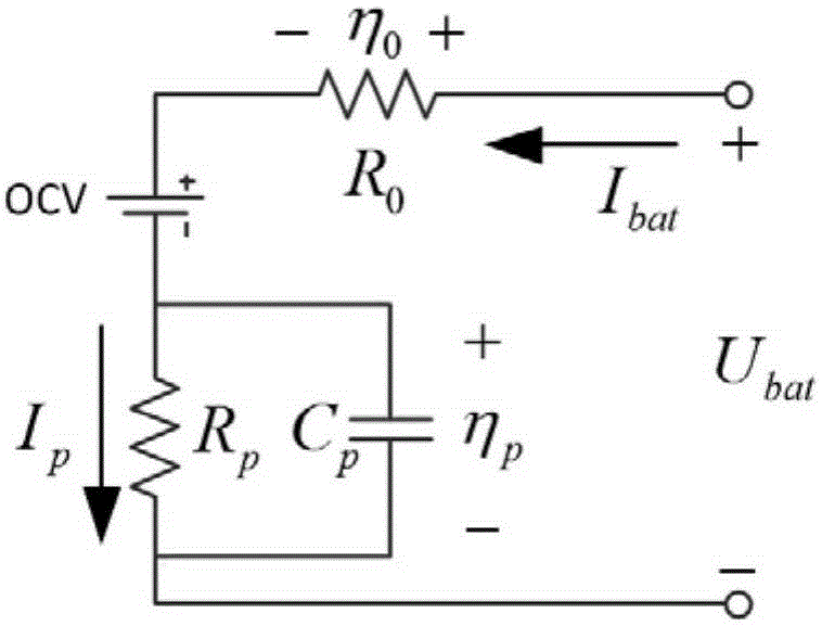
[0096] Specific implementation mode two: see Figure 1 to Figure 3 This embodiment is described. The difference between this embodiment and the energy storage battery detection method described in Embodiment 1 is that in step 12, the total power Power at each moment of testing the battery pack 1 is obtained. k The method is through the following formula:

[0097] power k =U bat,min (OCV k -U bat,min ) / R o,k (Formula 5),

[0098] Realized; among them, U bat,min Indicates the battery pack terminal voltage, and U bat,min =U' m,k , U' n,k , U′ p,k .

specific Embodiment approach 3

[0099] Specific implementation mode three: see Figure 1 to Figure 3 Describe this embodiment. The difference between this embodiment and the energy storage battery detection method described in the first embodiment is that in step 13, the power of each battery cell Power' at each time is obtained. k The method is through the following formula:

[0100] Power' k =U' bat,min (OCV' k -U' bat,min ) / R' i,k (Formula 6),

[0101] Realized; among them, U′ bat,min Indicates the battery cell terminal voltage, and U' bat,min =u' i,k 、u″ i,k , u″' i,k .


PUM


Abstract

The invention relates to the technical field of battery management, in particular to an energy storage battery detection method. The method solves the problem that the working performance of a battery pack under actual working conditions can not be detected through an existing battery pack detection technology. The method includes the set test steps that under given working conditions, a battery pack is kept static for 5 min, constant-current discharge is performed till discharge cut-off voltage U1 is reached, the battery pack is kept static for 1 h, constant-current charge is performed till charge cut-off voltage U2 is reached, constant-voltage charge is performed till the current is smaller than charge cut-off current, the battery pack is kept static for 1 h, discharge is performed under the working conditions till cut-off voltage U3 is reached, 0.05 C constant-current discharge is performed till cut-off voltage U4 is reached, and 0.5 C constant-current discharge is performed till discharge cut-off voltage U1 is reached. The evaluation parameters including open-circuit voltage, polarization internal resistance, polarization capacity, ohmic internal resistance, capacity parameters and power parameters of a battery module can be obtained by detecting the parameters including end voltage and total current and adopting an online parameter identification method, and then the parameters can be utilized for evaluating the battery pack. The method is mainly used for detecting the battery pack.

Description

technical field [0001] The invention belongs to the technical field of battery management. Background technique [0002] With the rapid development of the field of electrochemical energy storage represented by electric vehicles, how to detect the performance of energy storage battery packs is extremely important. The existing battery pack detection technologies and methods have a long detection cycle, and it is difficult to provide The detection parameters cannot be combined with the actual working conditions of the battery. The test conditions are single and inconsistent with the actual conditions. The final detection parameters cannot truly reflect the performance of the battery pack under actual working conditions. The present invention adopts different working conditions by corresponding to batteries used in different occasions. Using the designed working condition test cycle combined with online parameter identification technology, the working performance of the batter...

Claims


Application Information

Patent Timeline
Patent Type & Authority Applications(China)
IPC IPC(8): G01R31/36
Inventor 朱春波陈昊裴磊武国良徐冰亮
Owner STATE GRID CORP OF CHINA
Why Eureka
Try Eureka