Coaxial three-reflection telescope objective for planar view field without secondary blocking

A coaxial three-mirror and telescopic objective lens technology is applied in the field of optical imaging, which can solve the problems of large volume and secondary blocking, and achieve the effects of strong light-gathering ability, wide adaptable temperature range and good stray light suppression performance.

Active Publication Date: 2015-12-30
SUZHOU UNIV
View PDF5 Cites 6 Cited by
  • Summary
  • Abstract
  • Description
  • Claims
  • Application Information

AI Technical Summary

Problems solved by technology

While the above optical structures meet certain requirements, there are still problems such as large volume or secondary occlusion

Method used


Image

  • Coaxial three-reflection telescope objective for planar view field without secondary blocking
  • Coaxial three-reflection telescope objective for planar view field without secondary blocking
  • Coaxial three-reflection telescope objective for planar view field without secondary blocking

Examples


Embodiment 1

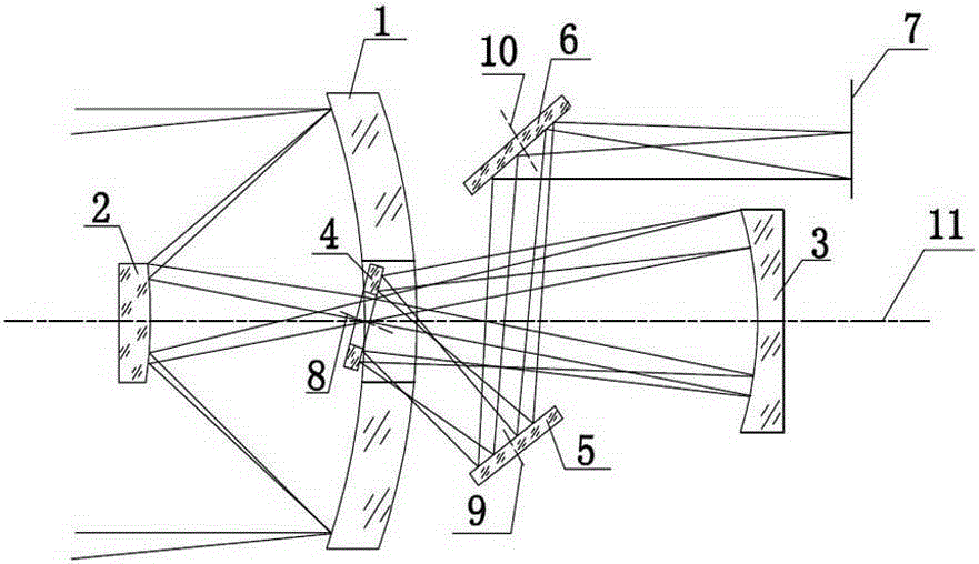
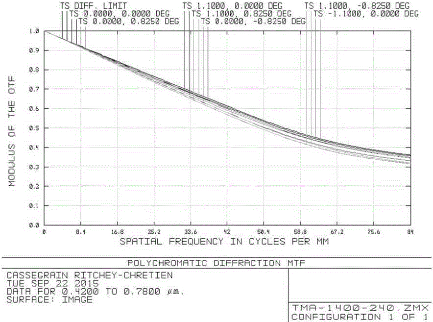
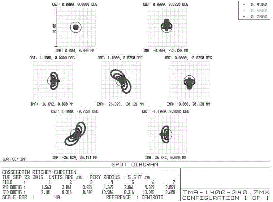
[0028] The technical solution of this embodiment is to provide a coaxial triple-mirror telescopic objective lens with no secondary obscuring surface field of view. The design parameters are: focal length 1400mm, full field of view angle 2.2°×1.65°, F number 7, working band 0.42μm ~0.78 μm.

[0029] See attached figure 1 , which is the optical path diagram of the telescopic objective provided in this embodiment. The primary mirror 1, the secondary mirror 2 and the third mirror 3 are coaxial, the aperture stop is located on the primary mirror 1, and the deflection mirror 4 is located between the secondary mirror 2 and the third mirror 3. After the incident light is reflected by the primary mirror 1 and the secondary mirror 2 in turn, a real image is formed between the secondary mirror 1 and the third mirror 3, and the reflected light passes through the central hole of the deflection mirror 4 without obstruction, and the three mirrors 3 pair a real image For relay imaging, the ...

Embodiment 2

[0038] This embodiment adopts the index requirements of Embodiment 1, that is, the focal length is 1400 mm, the full field of view is 2.2°×1.65°, the F number is 7, and the working band is 0.42 μm to 0.78 μm.

[0039] See attached Figure 6 , which is the imaging optical path diagram of the coaxial triple mirror telescopic objective lens provided in this embodiment. The primary mirror 1, the secondary mirror 2 and the third mirror 3 are coaxial, the aperture stop is located on the primary mirror 1, and the deflection mirror 4 is located between the secondary mirror 2 and the third mirror 3. After the incident light is reflected by the primary mirror 1 and the secondary mirror 2 in turn, a real image is formed between the secondary mirror 2 and the third mirror 3, and the reflected light passes through the center hole of the deflection mirror 4 without obstruction, and the three mirrors 3 pair a real image For relay imaging, the reflected light is incident on the clear apertur...


PUM


Abstract

The invention discloses a coaxial three-reflection telescope objective for a planar view field without secondary blocking. The telescope objective comprises a main lens, a secondary lens, a tertiary lens, a deflection mirror, a foldable plane mirror and a focal plane. Rotation symmetric axes of the main lens, the secondary lens and the tertiary lens coincide with a main optical axis, and an aperture diaphragm is placed on the main lens. The main lens and the tertiary lens are both ellipsoid faces, and the secondary lens is a hyperboloid. The deflection mirror is arranged on an emergent light path of the tertiary lens, the normal of the deflection mirror inclines relative to the main optical axis, and an image surface is led out of the optical axis. By reasonably arranging the position of an exit pupil, secondary blocking is not generated on the deflection mirror. The problems that in an existing coaxial three-reflection system, a detector is difficult to install and secondary blocking exists in the planar view field are solved. The telescope objective has the advantages of being long in focal length, large in aperture, little in blocking, small in size, low in weight, simple in structure, wide in work waveband and good in imaging quality, and is suitable for staring cameras, video cameras, front lens of imaging spectrographs and other optical imaging fields.

Description

technical field [0001] The invention relates to a telescopic objective lens which can be used for a staring camera, a video camera, and a front objective lens of an imaging spectrometer, in particular to a coaxial triple-mirror telescopic objective lens with no secondary obscuration surface field of view, which belongs to the technical field of optical imaging. Background technique [0002] With the continuous development of technologies such as aspheric surface processing and adjustment, total reflection structures are widely used in the field of optical long-distance imaging, typically with two-mirror and three-mirror structures. The two-mirror structure has few free parameters for correcting aberrations, so it is difficult to take into account the requirements of field of view, relative aperture, volume and weight. Based on the catadioptric structure of the two mirrors, a lens correction group is added to the object side or image side of the two coaxial mirrors to correct...

Claims


Application Information

Patent Timeline
Patent Type & Authority Applications(China)
IPC IPC(8): G02B17/06G02B23/02
CPCG02B17/0652G02B17/0657G02B23/02
Inventor 韩琳沈为民傅丹鹰赵知诚孙雯毛保奇
Owner SUZHOU UNIV
Why Eureka
Try Eureka