
Compact long focal length four-mirror telephoto objective

A telescopic objective lens and mirror technology, applied in the field of space optical imaging detection, can solve the problems of weak stray light suppression capability of the system and complex optical system, and achieve the effects of strong stray light suppression capability, small optical volume, and reduced length requirements.

Pending Publication Date: 2018-04-27
SUZHOU UNIV
View PDF0 Cites 14 Cited by
  • Summary
  • Abstract
  • Description
  • Claims
  • Application Information

AI Technical Summary

Problems solved by technology

[0003] Space remote sensing imaging systems often use reflective structures, which have the advantages of no chromatic aberration, insensitivity to temperature changes, and easy weight reduction. Reflective systems mainly include two-reflective systems and three-reflective systems. Reflection systems usually need to add lens compensation groups, and the system’s ability to suppress stray light is weak; three-reflection systems have more degrees of freedom in optimization and are easy to suppress stray light, etc. Many space camera optical systems use coaxial three-reflection structures. Secondary occlusion and shortening the size of the system, it is usually necessary to add multiple plane mirrors to fold the optical path, making the optical system complex and shortening the size is limited

Method used


Image

  • Compact long focal length four-mirror telephoto objective
  • Compact long focal length four-mirror telephoto objective
  • Compact long focal length four-mirror telephoto objective

Examples


Embodiment 1

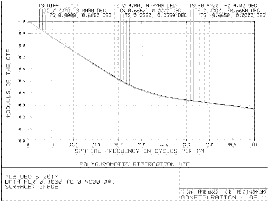
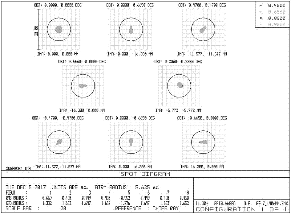
[0021] This embodiment provides a compact telescopic objective with long focal length and four mirrors. The working wavelength of the objective lens is 400-900 nm, the effective focal length is 1406 mm, the diameter of the entrance pupil is 200 mm, and the full field of view is 0.94°×0.94°.

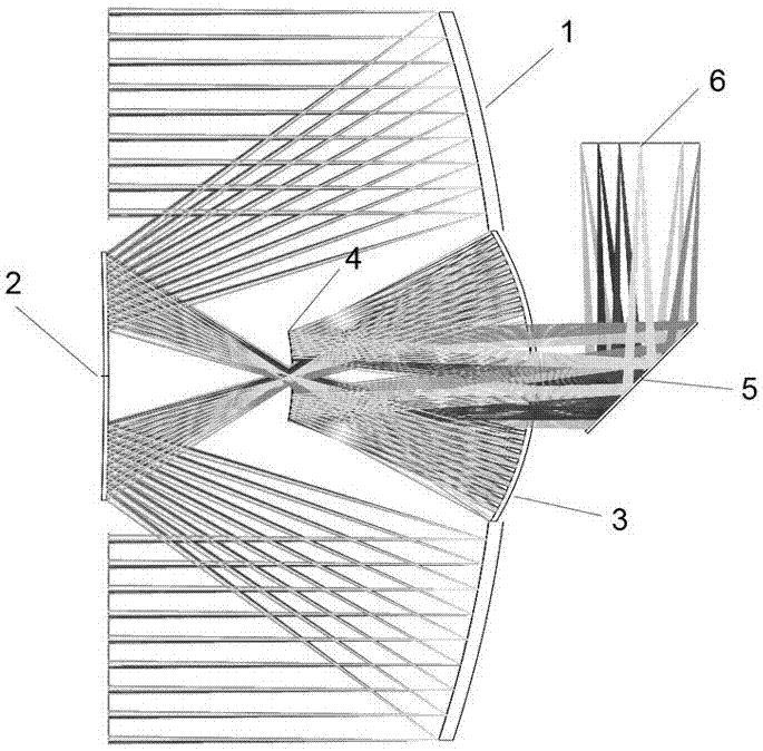
[0022] See attached figure 1 , which is a schematic structural view of a compact long focal length four-mirror telescopic objective lens system provided in this embodiment. According to the incident direction of light, it includes an elliptical surface primary mirror 1, a hyperboloid secondary mirror 2, an elliptical surface three mirrors 3, Ellipse four mirrors 4, plane mirrors 5 and focal plane 6, its primary mirror 1, secondary mirror 2, three mirrors 3, and four mirrors 4 are symmetrical to the main optical axis, and the optical system adopts a structure with an intermediate real image, without The secondary obscuration draws out the image plane, facilitating installation and placemen...


PUM


Abstract

The invention discloses a compact long focal length four-mirror telescope objective. According to the incident direction of light, the telescope objective is composed of an elliptical main mirror, a hyperboloid secondary mirror, an elliptical third mirror, an elliptical fourth mirror, a plane mirror and a focal plane in order. The main mirror, the secondary mirror, the third mirror and the fourthmirror are in a main optical axis symmetrical structure, and view field imaging without secondary masking face is formed. An aperture diaphragm is located at the main mirror, and the fourth mirror islocated at a primary real image formed by the main mirror and the secondary mirror. After incident light from a scene is reflected by the main mirror and the secondary mirror, an intermediate real image is formed in front of the third mirror. After the light is reflected by the third mirror and the fourth mirror, the light passes through the center hole of the third mirror without block, and the light is imaged at the focal plane through a plane mirror turning optical path. According to the invention, view field imaging without secondary masking face is realized by reasonably controlling the exit pupil position and the distance between the mirrors; and the system has the advantages of long focal length, long short barrel, small size, compact structure, good imaging quality, low processingcost and the like, and meets the needs of light and small optical systems in imaging fields such as space remote sensing video cameras and imaging spectrometer front objectives.

Description

technical field [0001] The invention relates to a compact telescopic objective lens with long focal length and four mirrors, which can be applied to the telescopic objective lens of low-cost, light and small space cameras of micro-nano satellites, pre-imaging systems of spectrometers, etc., and belongs to the technical field of space optical imaging detection. Background technique [0002] At present, small satellites are gradually becoming miniaturized, and 1-100kg micro-nano satellites have become a hot spot in the aerospace field because of their advantages such as lower development costs, shorter cycle times, more flexibility, and small size. In terms of space remote sensing detection, it can realize fast, accurate and real-time earth observation in a large area, and is widely used in communication fields, space remote sensing, military investigation and other aspects. In order to adapt to the micro-nano satellite platform and obtain higher image quality, the optical pay...

Claims


Application Information

Patent Timeline
IPC IPC(8): G02B23/06G02B17/06
CPCG02B17/0652G02B23/06
Inventor 陈丽沈为民傅丹鹰赵知诚刘莉
Owner SUZHOU UNIV
Learn More