Novel planar Gunn diode and preparation method thereof

A Gunn diode and planar technology, which is applied in the field of new planar Gunn diode and its preparation, can solve the problems of lower reliability, difficult working frequency, unfavorable application, etc., and achieve the goal of improving device performance, increasing transmission frequency, and reducing mutual interference Effect

Inactive Publication Date: 2015-12-30
SHANDONG UNIV
View PDF6 Cites 7 Cited by
  • Summary
  • Abstract
  • Description
  • Claims
  • Application Information

AI Technical Summary

Problems solved by technology

However, whether it is a vertical Gunn device or a planar Gunn device, their electrode spacing is the same throughout the device, which results in a Gunn device that can only generate a single frequency signal. If multiple frequency signals are required at the same time, it needs to be used Multiple devices, which will increas

Method used


Image

  • Novel planar Gunn diode and preparation method thereof
  • Novel planar Gunn diode and preparation method thereof
  • Novel planar Gunn diode and preparation method thereof

Examples


Embodiment 1

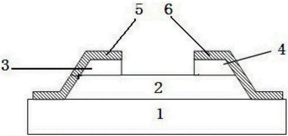
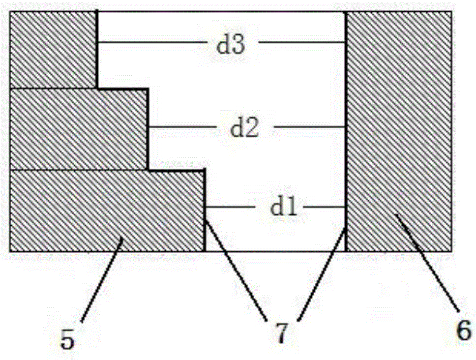
[0045] A new type of planar Gunn diode, comprising: an insulating substrate 1, a channel layer 2, and a first electrode part and a second electrode part arranged on the channel layer 2 from bottom to top, the first At least one of the electrode part, the second electrode part, and the channel formed by the first electrode part and the second electrode part is integrated, and the electrode edge 7 of the first electrode part is connected to the second electrode Part of the electrode edges 7 are not parallel.

[0046] The electrode edge 7 of the first electrode part refers to the intersection line between the surface of the first electrode part opposite to the second electrode part and the channel layer 2. Similarly, the second electrode part The electrode edge 7 refers to the intersection line between the surface of the second electrode portion opposite to the first electrode portion and the channel layer 2 .

[0047] The advantage of the design here is that the electrode edge ...

Embodiment 2

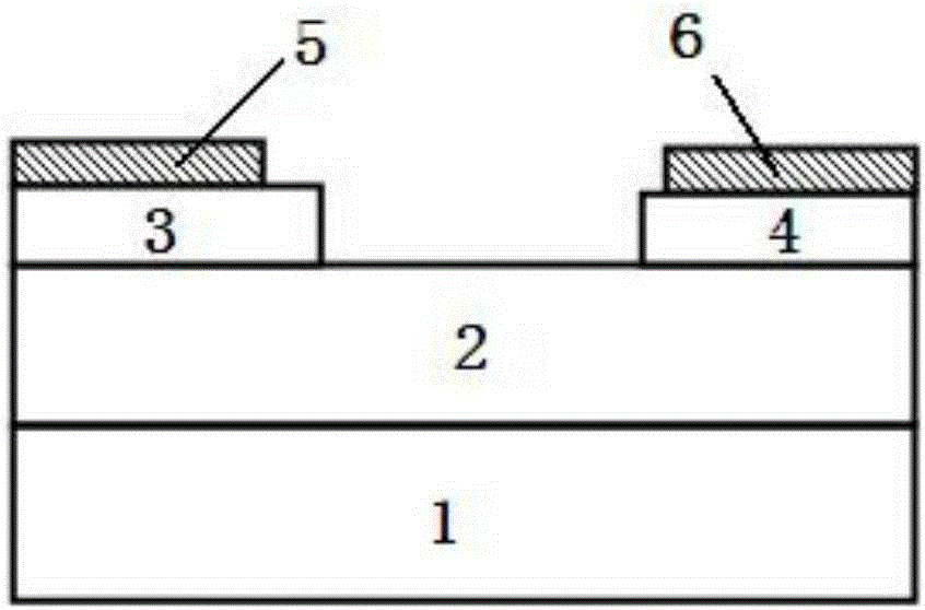
[0056] According to a new type of planar Gunn diode described in Embodiment 1, the difference is that the first electrode part includes a first electrode 5 and a first capping layer 3, and the first capping layer 3 is arranged on the first Between the electrode 5 and the channel layer 2, the second electrode part includes a second electrode 6 and a second cap layer 4, and the second cap layer 4 is arranged between the second electrode 6 and the channel layer. Between layers 2, the first electrode 5 does not cover the first capping layer 3, and the second electrode 6 does not cover the second capping layer 4, as image 3 shown.

Embodiment 3

[0058] According to a new type of planar Gunn diode described in Embodiment 1, the difference is that the first electrode part includes a first electrode 5 and a first capping layer 3, and the first capping layer 3 is arranged on the first Between the electrode 5 and the channel layer 2, the second electrode part includes a second electrode 6 and a second cap layer 4, and the second cap layer 4 is arranged between the second electrode and the channel layer 6. Between layers 2, the first electrode 5 does not cover the first capping layer 3, and the second electrode 6 covers the second capping layer 4 to contact the channel layer 2, as Figure 4 shown.


PUM


Abstract

The invention relates to a novel planar Gunn diode and a preparation method thereof. The novel planar Gunn diode comprises an insulating substrate and a channel layer which are arranged from bottom to top in sequence, as well as a first electrode part and a second electrode part which are arranged on the channel layer, wherein at least one of the first electrode part, the second electrode part and the channel formed by the first electrode part and the second electrode part is integrated; the electrode edge of the first electrode part and the electrode edge of the second electrode part are not parallel; at least two intervals exist between the electrode edge of the first electrode part and the electrode edge of the second electrode part, so that signals of multiple frequencies can be generated at the same time, on one hand, the novel planar Gunn diode can be applied to the fields of multifrequency radar, color terahertz imaging and the like requiring signal sources of multiple frequencies simultaneously, and on the other hand, by using the own frequency mixing effect of the novel planar Gunn diode, a high-frequency signal, of which the frequency is the sum of such signal frequencies can be generated, so that the transmitting frequency of a device is increased greatly.

Description

technical field [0001] The invention relates to a novel planar Gunn diode and a preparation method thereof, belonging to the technical field of diodes in microwave devices. Background technique [0002] The Gunn diode was first discovered in 1963 by J.B. Gunn. The Gunn diode utilizes the differential negative resistance effect of certain semiconductor materials (such as GaAs, InP, GaN, etc.) when electrons transition from low-energy valleys to high-energy valleys because the effective mass of electrons increases and the saturation drift speed decreases. . [0003] The traditional Gunn device is to form electrical contact on the front and back of the bulk material, and the current flows perpendicular to the electrode plane, so it can be called a vertical Gunn device. As a small high-frequency signal source, the vertical Gunn device is widely used in radar, communication, space exploration and other fields. However, the vertical Gunn device has many disadvantages, such as: ...

Claims


Application Information

Patent Timeline
IPC IPC(8): H01L29/861H01L29/40H01L29/41H01L29/10H01L21/329
CPCH01L29/10H01L29/40H01L29/41H01L29/6609H01L29/861
Inventor 宋爱民王汉斌王卿璞
Owner SHANDONG UNIV
Why Eureka
Try Eureka