Ejector pin structure of laminating machine

A laminator and thimble technology, applied in lamination, lamination devices, layered products, etc., can solve problems such as inconsistent cross-linking degrees, achieve consistent EVA cross-linking degrees, and ensure consistency

Inactive Publication Date: 2015-12-30
EGING PHOTOVOLTAIC TECHNOLOGY CO LTD
View PDF0 Cites 3 Cited by
  • Summary
  • Abstract
  • Description
  • Claims
  • Application Information

AI Technical Summary

Problems solved by technology

[0004] The technical problem to be solved by the present invention is: in order to solve the problem that the thimble of the traditional laminator is a circular arc top, there will be a certain gap between the thimble and the laminate, and the cross-li

Method used


Image

  • Ejector pin structure of laminating machine
  • Ejector pin structure of laminating machine
  • Ejector pin structure of laminating machine

Examples


Embodiment 1

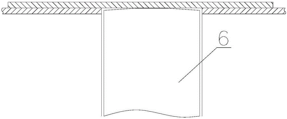
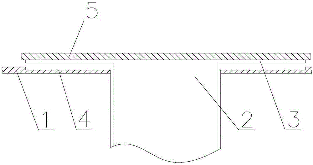
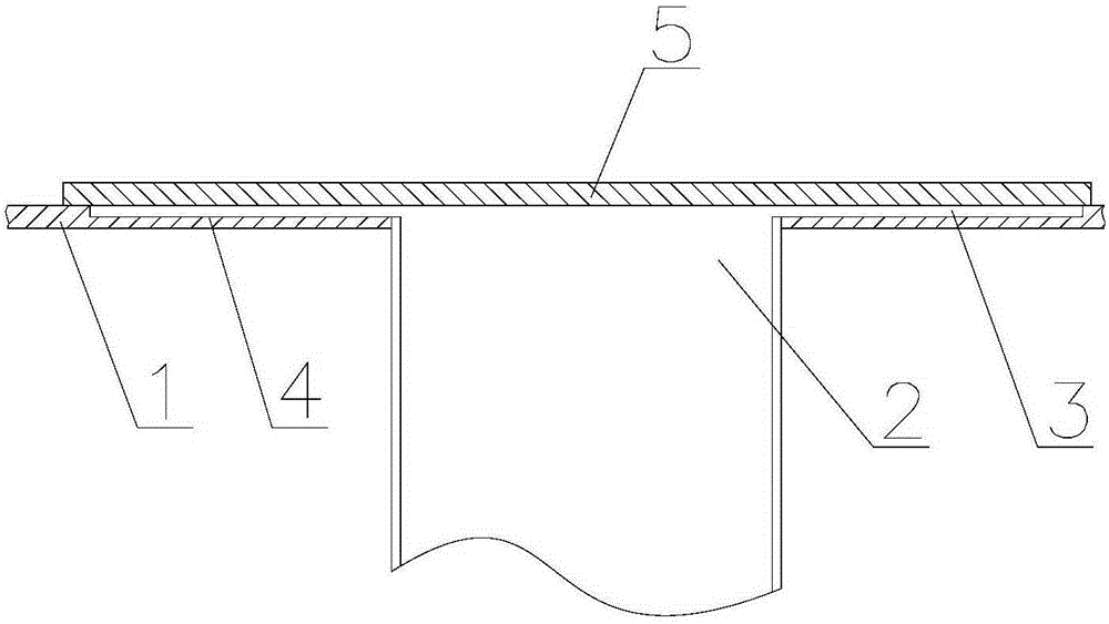
[0019] Such as Figure 2-4 As shown, a thimble structure of a laminator, the laminator has a heating plate 1, a guide hole is provided on the heating plate 1, the upper surface of the heating plate 1 is a plane, and the thimble structure includes a guide hole The matching needle body 2 and the platform 3 covered on the top of the needle body 2, the upper surface of the platform 3 is a plane, the needle body 2 is inserted in the guide hole, and the heating plate 1 is located on the The part directly below the platform 3 is provided with a depression 4 that matches the platform 3. When the lower surface of the platform 3 is in contact with the bottom surface of the depression 4, the upper surface of the platform 3 is flush with the upper surface of the heating plate 1. , to ensure the consistency of heat transfer, the material of the needle body 2 and the platform 3 is the same as that of the heating plate 1, the needle body 2 is cylindrical, and the platform 3 is cylindrical. I...


PUM


Abstract

The invention relates to the technical field of solar battery cell encapsulation, particularly to an ejector pin structure of a laminating machine. The laminating machine comprises a heating plate, wherein a guide hole is formed in the heating plate; the upper surface of the heating plate is a plane. The ejector pin structure comprises an ejector pin body matched with the guide hole and a platform covering the top of the ejector pin body, wherein the upper surface the platform is a plane; the ejector pin body is inserted in the guide hole; a sunken part matched with the platform is arranged at the part, right below the platform, of the heating plate; when the lower surface of the platform is in contact with the bottom surface of the sunken part, the upper surface of the platform and the upper surface of the heating plate are level. According to the ejector pin structure of the laminating machine provided by the invention, the materials of the ejector pin body, the platform and the heating plate are the same, so that consistency of heat transfer among the ejector pin part and other parts of the heating plate is guaranteed when the heating plate is heated; the platform is added at the top of the ejector pin body, so that pieces to be subjected to lamination are uniformly heated when the laminating machine is heated, consistency of EVA crosslinking degree in the pieces to be subjected to lamination is guaranteed, and the properties of a solar component are guaranteed.

Description

technical field [0001] The invention relates to the technical field of solar cell chip packaging, in particular to a thimble structure of a laminating machine. Background technique [0002] Because the output power of a single cell is too small to meet the conventional electricity demand, it needs to be packaged into components to increase its output power. Encapsulation is a key step in the production of solar cells. Without a good encapsulation process, even the best cells cannot produce good modules. The packaging of the battery can not only ensure the life of the battery, but also enhance the resistance of the battery. At present, lamination machines are widely used in solar cell module packaging equipment, which is an important equipment for manufacturing solar cell modules. The EVA, solar cells, tempered glass, and back film (TPT, PET, etc.) are pressed into a rigid whole by a laminator under high temperature and vacuum conditions. The lamination process is a key st...

Claims


Application Information

Patent Timeline
IPC IPC(8): H01L31/18H01L31/048B32B37/00
CPCB32B37/00H01L31/048H01L31/18Y02E10/50Y02P70/50
Inventor 安全长
Owner EGING PHOTOVOLTAIC TECHNOLOGY CO LTD
Why Eureka
Try Eureka