Efficient microstrip antenna based on non-periodic artificial magnetic conductor structure

A technology of artificial magnetic conductor and microstrip antenna is applied in the directions of antenna, radiating element structure, antenna grounding switch structure connection, etc., which can solve the problems of only radiation efficiency and poor cross-polarization suppression effect, and achieves easy processing and cost and the effect of small weight and simple structure

Active Publication Date: 2015-12-30
NANJING UNIV OF SCI & TECH
View PDF3 Cites 19 Cited by
  • Summary
  • Abstract
  • Description
  • Claims
  • Application Information

AI Technical Summary

Problems solved by technology

But the radiation efficiency is only 83%, an...

Method used


Image

  • Efficient microstrip antenna based on non-periodic artificial magnetic conductor structure
  • Efficient microstrip antenna based on non-periodic artificial magnetic conductor structure
  • Efficient microstrip antenna based on non-periodic artificial magnetic conductor structure

Examples


Embodiment 1

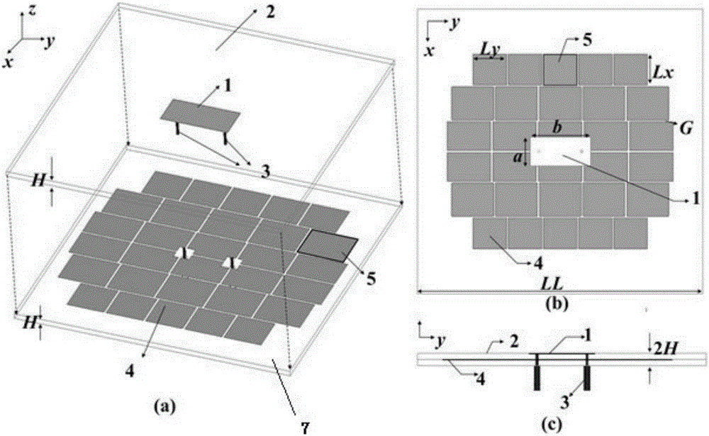
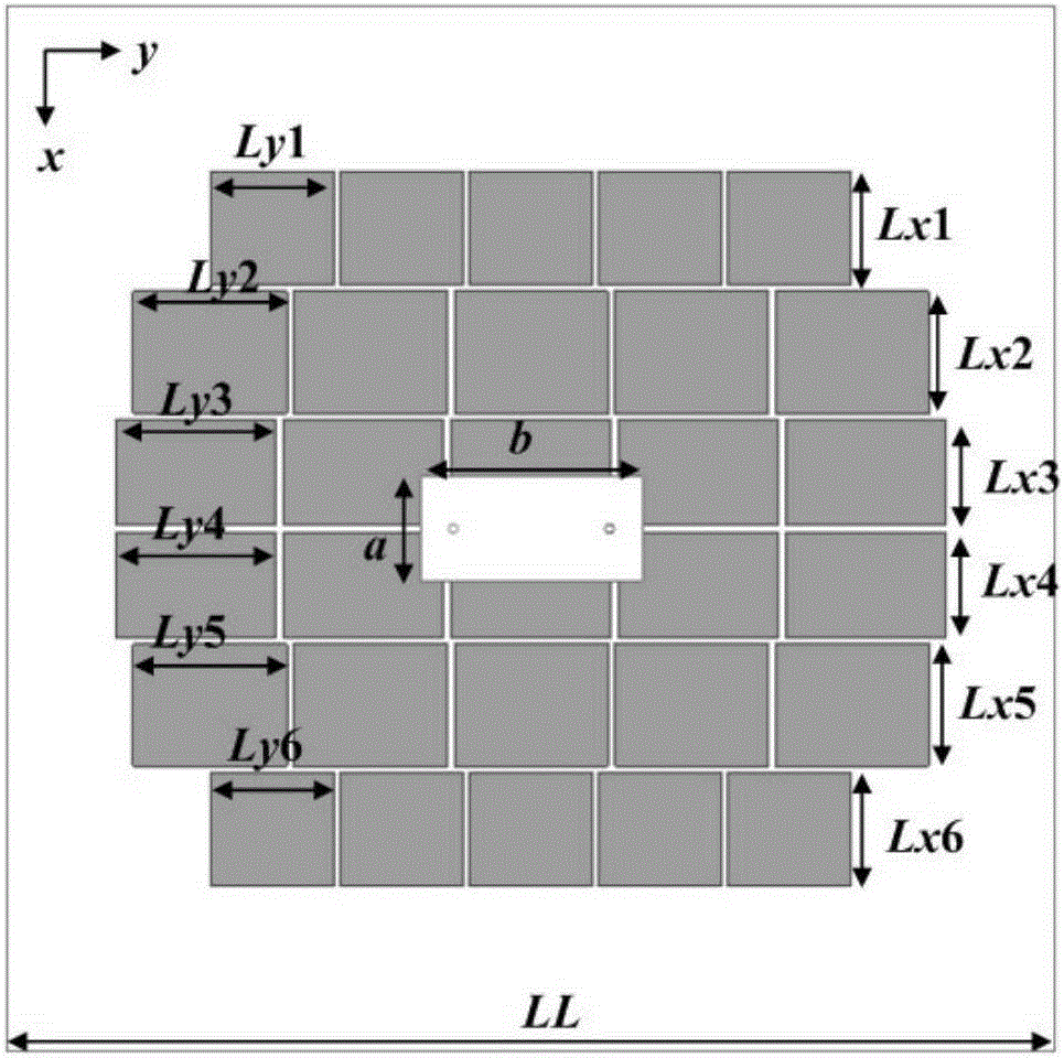
[0029] combine image 3 , the aperiodic artificial magnetic conductor reflector 4 is divided into 30 independent artificial magnetic conductor units 5, and the length Ly and width Lx of each artificial magnetic conductor unit 5 are not exactly the same, five artificial magnetic conductors in each row The length Ly and the width Lx of the units are respectively consistent, and the length and width of the artificial magnetic conductor units between different rows are not consistent. Among them, the length Ly of each row of artificial magnetic conductor units is ly1, ly2, ly3, ly4, ly5, ly6 from top to bottom, and the width Lx is lx1, lx2, lx3, lx4, lx5, lx6 from top to bottom, where ly1 =ly6, ly2=ly5, ly3=ly4, lx1=lx6, lx2=lx5, lx3=lx4.

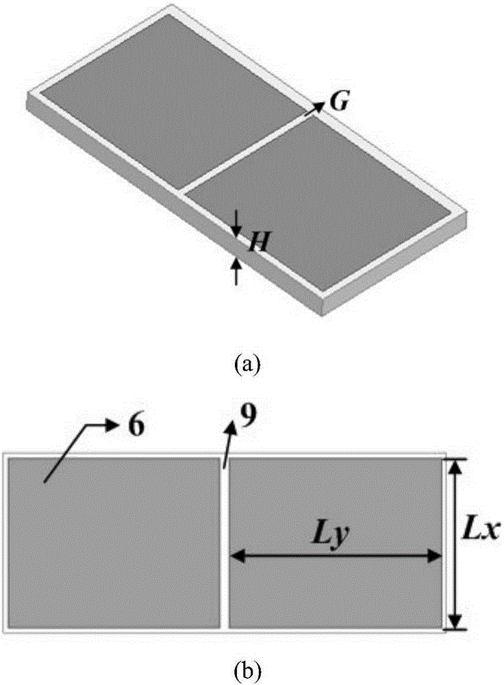
[0030] The length and width of the artificial magnetic conductor unit 5 are [0.05λ, 0.26λ], and the width of the narrow gap 9 is [0.001λ, 0.015λ]; the dielectric constant ε of the upper dielectric substrate 2 and the lower dielectric substrate...

Embodiment 2

[0042] combine Figure 7 , the non-periodic artificial magnetic conductor reflector 4 is divided into 12 independent artificial magnetic conductor units 5, and the length Ly and width Lx of each artificial magnetic conductor unit 5 are not exactly the same, three artificial magnetic conductor units in each row The length Ly and width Lx of each are consistent, and the length and width of the artificial magnetic conductor units between different rows are not consistent. Wherein, the length Ly of each row of artificial magnetic conductor units is ly1, ly2, ly3, ly4 from top to bottom, and the width Lx is lx1, lx2, lx3, lx4 from top to bottom, wherein ly1=ly4, ly2=ly3, lx1 = lx4, lx2 = lx3.

[0043] The length and width of the artificial magnetic conductor unit 5 are [0.05λ, 0.26λ], and the width of the narrow gap 9 is [0.001λ, 0.015λ]; the dielectric constant ε of the upper dielectric substrate 2 and the lower dielectric substrate 7 r are [2.2,10.2], and the thickness H is [0....


PUM

PropertyMeasurementUnit
Reflection coefficientaaaaaaaaaa
Relative bandwidthaaaaaaaaaa

Abstract

The invention provides an efficient microstrip antenna based on a non-periodic artificial magnetic conductor structure. The efficient microstrip antenna is composed of medium substrates which are laminated in a two-layer mode, and comprises a patch antenna, a metal floor, an artificial magnetic conductor reflection plate and coaxial feed probes. The patch antenna is printed at the upper surface of an upper-layer medium substrate, the metal floor is printed at the lower surface of a lower-layer medium substrate, the artificial magnetic conductor reflection plate is printed at the upper surface of the lower-layer mediums substrate, the coaxial feed probes are inserted into the artificial magnetic conductor reflection plate and the upper-layer medium substrate from the lower surface of the lower-layer medium substrate, and the two coaxial feed probes are connected with the patch antenna; the artificial magnetic conductor reflection plate is segmented into multiple independent artificial magnetic conductor units arranged in a matrix, and each artificial magnetic conductor unit is a rectangular metal patch; and the artificial magnetic conductor units arranged in a matrix are arranged to be symmetrical about an axis between two middlemost rows, each row of artificial magnetic conductor units have the same dimensions, and the dimensions of the artificial magnetic conductor units in different rows cannot be completely the same.

Description

technical field [0001] The invention relates to a microstrip antenna, in particular to a high-efficiency microstrip antenna based on an aperiodic artificial magnetic conductor structure. Background technique [0002] In recent years, artificial magnetic conductors are one of the research hotspots in the field of microwave and millimeter waves. Utilizing its unique surface wave bandgap characteristics and the in-phase reflection characteristics of plane waves, the performance of the antenna can be effectively improved. F.Yang and Y.Rahmat-Samii et al. applied the artificial magnetic conductor structure around the microstrip antenna to suppress the propagation of surface waves, increase the gain of the antenna, and reduce the back lobe. At the same time, using it as the reflecting surface of the dipole antenna and the helical coil antenna can make the antenna close to the surface of the artificial magnetic conductor structure and realize a low-profile antenna. In addition, A...

Claims


Application Information

Patent Timeline
IPC IPC(8): H01Q1/50H01Q1/38H01Q19/185H01Q15/14
Inventor 车文荃陈东旭杨琬琛金华燕杨亚洋王威
Owner NANJING UNIV OF SCI & TECH
Why Eureka
Try Eureka