Integrated heat dissipation and dust removing distribution box

A distribution box, integrated technology, applied in the field of heat dissipation and dust removal integrated distribution box, can solve the problems of poor heat dissipation, dusty, short circuit and so on

Inactive Publication Date: 2015-12-30
STATE GRID CORP OF CHINA +2
View PDF5 Cites 8 Cited by
  • Summary
  • Abstract
  • Description
  • Claims
  • Application Information

AI Technical Summary

Problems solved by technology

At present, the method and structure adopted for heat dissipation of the electrical components in the distribution box have the following defects: 1. Since the distribution box is generally high in height, vertical ventilation is adopted, the air path is long, and the cold air at the end of the air path has been blocked. Heating, so the temperature in the distribution box is still high, and the heat dissipation effect is poor, resulting in shortened service life of electrical components; 2. There is more dust at the air inlet of the air duct, so that the wind entering the distribution box carries more dust; 3. 1. After the electrical components are used for a long time, dust is easy to accumulate in the depressions and irregular protrusions of the electrical components, reducing the service life of the electrical components and forming a safety hazard (possibly causing a short circuit); 4. The air volume of the air circuit is not adjusted. Mechanism, high energy consumption, low cooling efficiency

Method used


Image

  • Integrated heat dissipation and dust removing distribution box
  • Integrated heat dissipation and dust removing distribution box
  • Integrated heat dissipation and dust removing distribution box

Examples


Embodiment Construction

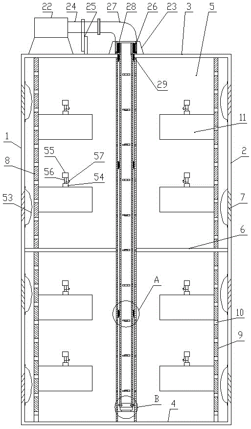
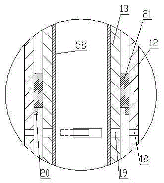
[0028] Such as Figure 1-Figure 7 As shown, the heat dissipation and dust removal integrated distribution box of the present invention includes a box in the shape of a cuboid, and the box consists of a left side panel 1, a right side panel 2, a top panel 3, a bottom panel 4, a rear side panel 5 and a box door (Fig. not shown in ), a partition 6 is arranged horizontally between the left side panel 1 and the right side panel 2, shutters 7 are respectively arranged on the left side panel 1 and the right side panel 2, and the inner wall of the left side panel 1 and the right side panel 2 The inner wall is provided with a cleaning structure at the shutter 7, and a left vertical board 8 and a right vertical board 9 are arranged between the top board 3 and the bottom board 4, the left vertical board 8 is parallel to and adjacent to the left side board 1, and the right vertical board 9 is connected to the The right side plate 2 is parallel and adjacent, and the left vertical plate 8 a...


PUM


Abstract

An integrated heat dissipation and dust removing distribution box comprises a cuboid-shaped box body, wherein the box body comprises a left side plate, a right side plate, a top plate, a baseplate, a rear side plate and a box door, wherein shutters are arranged on the left side plate and the right side plate respectively; soot cleaning structures are arranged on the shutters on the inner walls of the left side plate and the right side plate; a left standing plate and a right standing plate are arranged between the top plate and the baseplate, and are parallel and adjacent to each other; the right standing plate and the right side plate are parallel and adjacent to each other; the air extracting holes are uniformly formed in the left standing plate and the right standing plate; electric elements are arranged on the right side of the left standing plate and the left side of the right standing plate; rotary dust blowing mechanisms are arranged at the tops of the electric elements; a wind volume rotational adjusting mechanism is arranged between the center of the top plate and that of the baseplate. The integrated heat dissipation and dust removing distribution box has the advantages that the structure is simple; the operation is easy; the radiating effect is high; the energy consumption is low; the reliability is high; the dust-proof effect is good; the temperature of the electric element in the box body can be adjusted to meet the requirement of a favorable operating state by adjusting the wind-drawing volume, so as to prolong the service lives of the electric elements.

Description

technical field [0001] The invention relates to an electrical device, in particular to an integrated distribution box for heat dissipation and dust removal. Background technique [0002] The distribution box is a commonly used electrical equipment in the power industry. The heat generated by the electrical components installed in the distribution box needs to be discharged continuously to ensure the normal operation of the electrical components. At present, the method and structure adopted for heat dissipation of the electrical components in the distribution box have the following defects: 1. Since the distribution box is generally high in height, vertical ventilation is adopted, the air path is long, and the cold air at the end of the air path has been blocked. Heating, so the temperature in the distribution box is still high, and the heat dissipation effect is poor, resulting in shortened service life of electrical components; 2. There is more dust at the air inlet of the ...

Claims


Application Information

Patent Timeline
Patent Type & Authority Applications(China)
IPC IPC(8): H02B1/28H02B1/56
CPCH02B1/28H02B1/565
Inventor 常颖任伟平周宇航刘会卢树娟卢磊刘亚辉
Owner STATE GRID CORP OF CHINA
Why Eureka
Try Eureka