Multi-level inverter circuit and control method thereof
A multi-level inverter and inverter technology, applied in the field of circuits, can solve problems such as no discharge technical solutions, and achieve the effect of low cost and simple operation
- Summary
- Abstract
- Description
- Claims
- Application Information
AI Technical Summary
Problems solved by technology
Method used
Image


Examples
Embodiment 1
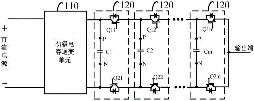
[0055] figure 2 It is a schematic structural diagram of an inverter circuit provided by Embodiment 1 of the present invention, and this embodiment is applicable to the case of discharging the floating capacitance in a multilevel inverter. Such as figure 2 As shown, the multilevel inverter circuit includes a primary capacitor inverter unit 110, cascaded m level switching units 120 and a first discharge circuit 130;
[0056] The input terminal of the primary capacitor inverter unit 110 is connected to the DC power supply. Those skilled in the art can understand that this may include the situation where the primary capacitor inverter unit 110 is directly connected to the battery board, or it may be the case where the battery board and the primary capacitor inverter A booster circuit is provided between the units 110 .
[0057] The level switching unit 120 includes a first capacitor, a first switch tube and a second switch tube, wherein the first end of the first capacitor is ...
Embodiment 2
[0065] On the basis of the above embodiments, this embodiment, as a preferred embodiment, specifically provides the discharge circuit diagram when the first discharge circuit is connected between two adjacent level switching units, specifically including two Condition. In the first case, the first connection end of the first discharge circuit is electrically connected to the first end of the first capacitor in the i-th level switching unit, and the second connection end of the first discharge circuit is electrically connected to the i+1th level switching unit. The second end of the first capacitor in the level switching unit is electrically connected. Wherein i is a positive integer, and i+1 is less than or equal to m.
[0066] image 3Schematic structure diagram of an inverter circuit provided for Embodiment 2 of the present invention Figure 1 , for the convenience of representation, in this embodiment, the case where i is equal to 1 is used for specific description, such...
Embodiment 3
[0075] On the basis of the above embodiments, this embodiment is taken as a preferred embodiment, and specifically provides that when the first discharge circuit 130 is connected to a discharge line between non-adjacent two-stage level switching units.
[0076] If the first connection end of the first discharge circuit 130 is electrically connected to the first end of the first capacitor in the i-th level switching unit, the second connection end of the first discharge circuit 130 is electrically connected to the first end of the j-th level switching unit. The second end of a capacitor is electrically connected, and when the first capacitor in the i-th level switching unit is discharged, the second end of the first capacitor in the i-th level switching unit is controlled to switch to the j-th level The switch tube between the second ends of the first capacitor in the unit is turned on, and the first discharge circuit 130 is turned on; when the first capacitor in the j level swi...
PUM
 Abstract
Description
Claims
Application Information
 - R&D
- Intellectual Property
- Life Sciences
- Materials
- Tech Scout
- Unparalleled Data Quality
- Higher Quality Content
- 60% Fewer Hallucinations
Browse by: Latest US Patents, China's latest patents, Technical Efficacy Thesaurus, Application Domain, Technology Topic, Popular Technical Reports.
© 2025 PatSnap. All rights reserved.Legal|Privacy policy|Modern Slavery Act Transparency Statement|Sitemap|About US| Contact US: help@patsnap.com