Plant holder and transplantation device

A retainer and plant technology, which is applied in the fields of botanical equipment and methods, container cultivation, gardening, etc., can solve the problems of incomplete prevention, failure to enter the retaining hole, deterioration, etc., and achieve the effect of improving workability and easy insertion.

Inactive Publication Date: 2015-12-30
TSUBAKIMOTO CHAIN CO
View PDF12 Cites 0 Cited by
  • Summary
  • Abstract
  • Description
  • Claims
  • Application Information

AI Technical Summary

Problems solved by technology

[0015] As described above, in conventional cultivation equipment like Patent Documents 1 and 2, when plants are transplanted into the holding holes of the cultivation board, some or all of the roots may not enter the holding holes or remain in the holding holes. , there is a possibility that the plant cannot be transplanted to the holding hole, or, even if the plant can be transplanted, part or all of the root does not protrude below the holding hole
[0016] In this way, as described in Patent Document 2, although it can be alleviated to a certain extent by using the suction unit that attracts the roots of the plants and makes them pass through the holding holes, the complexity of the equipment will be brought. When the root of the hole is pressed against the inner surface of the holding hole due to the large amount of root or its expansion, part or all of the root may be stagnated due to the resistance between the inner surface of the holding hole and cannot be extended to the bottom of the holding hole. State, if the attraction is enhanced, it is possible that the attraction will damage the roots
[0017] As described in Patent Document 3, although the state that part or all of the root does not extend below the holding hole can be alleviated to some extent even by adopting a structure that can enlarge the holding hole, the diameter of the holding hole has to be smaller than that of the convex hole. The diameter of the rim cannot be completely prevented from being in the above-mentioned state
[0018] In addition, in the existing cultivation equipment, there is a problem that when the leaves of the plant expand laterally, the leaves may droop and come into contact with the transplanting device, or may come into contact with the cultivation board or the cultivation liquid after transplantation, and the leaves may Subject to damage, discoloration, deterioration, or withering, which would impair its commercial value
[0019] In this way, as described in Patent Document 3, although the plants held on the support body are supported on the holding holes of the cultivation plate through the plant holder having a flange on the top, thereby the leaves can be prevented from drooping to a certain extent by the flange, However, there is a problem that it is necessary to change the operating unit of the plant holder according to the size and shape of the flange, and at the same time, it is difficult to enlarge the flange enough to prevent the leaves from being damaged due to operational constraints.
[0020] Moreover, in the known techniques described in Patent Documents 4 and 5, it is necessary to provide a movable mechanism at the tip of the device that operates the plant holder of the transplanting device, and there is a problem that a complicated mechanism is required.
[0021] In addition, there is a problem that the device for operating the plant holder may contact the plant and damage the plant, and when the plant holder is operated by a multi-joint robot device, since it is necessary to provide a movable mechanism at the top, Therefore, the top load increases, and the scale and cost of the equipment increase.

Method used


Image

  • Plant holder and transplantation device
  • Plant holder and transplantation device
  • Plant holder and transplantation device

Examples


Embodiment

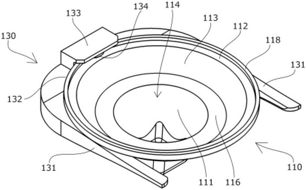
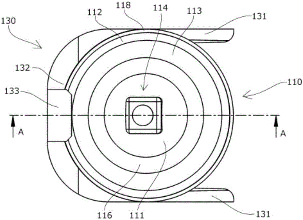
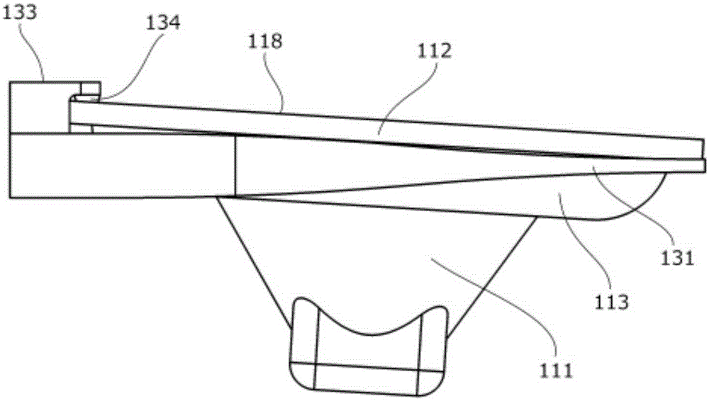
[0061] based on Figure 1 to Figure 7 One embodiment of the plant holder and transplantation device of the present invention will be described.

[0062] Plant holder 110 which is an embodiment of the present invention is integrally formed of resin or the like with a substantially uniform thickness, and has flange portion 112 , placement portion 113 , and fitting portion 111 from above.

[0063] The inner surface of the fitting portion 111 has a tapered plant support hole 114 , and the outer periphery is formed in a tapered shape that can be inserted into the holding hole 121 of the cultivation plate 120 from above.

[0064] In this embodiment, in order to maintain strength, the bottom part of the fitting part 111 is formed in a thick square shape.

[0065] The outer diameter of the placement portion 113 is larger than that of the fitting portion 111 , and has a flat portion 116 formed in a planar shape below that contacts the periphery of the holding hole 121 of the cultivati...


PUM


Abstract

The purpose of the present invention is to provide a plant holder which, with a simple configuration, allows for roots of plant stocks to pass through and below a retention hole without being damaged and prevents leaves from being damaged as a result of hanging down, as well as makes it possible to improve workability when automating transplantation and harvesting, without touching and damaging the plant stocks. A plant holder (110) comprises the following: a fitting section (111) that has a plant stock bearing hole (114) on an inner surface thereof and is fitted to a retention hole (121) of a cultivation panel (120); a placement section (113) provided thereabove; and a flange section (112) provided thereabove. The outer diameter of the flange section (112) is formed so as to be larger than the outer diameter of the placement section (113). The outer diameter of the placement section (113) is formed so as to be larger than the outer diameter of the retention hole (121).

Description

technical field [0001] The present invention relates to a plant holder and a transplanting device for holding and moving the plant holder. At least a part of the outer periphery of the plant holder is fitted into a holding hole of a cultivation plate, and has a plant for directly or indirectly supporting the plant The support hole relates to, for example, a plant holder and a transplanting device suitable for transplanting plants according to their growth or automating harvesting of grown plants in hydroponic cultivation equipment such as a plant factory. Background technique [0002] In the past, the following hydroponic cultivation equipment is known. In a plant factory or the like, a plant is held on a holding member, for example, a cultivation plate having a plurality of holding holes, and the roots of the plants extending below the holding holes of the cultivation plate are immersed in the into the cultivation liquid or the like, or spray the cultivation liquid or the l...

Claims


Application Information

Patent Timeline
Patent Type & Authority Applications(China)
IPC IPC(8): A01G31/00A01G9/02A01G31/02
CPCA01G9/083A01G9/086A01G9/0299A01G31/02
Inventor 河野浩二平井达也冈崎由大原均
Owner TSUBAKIMOTO CHAIN CO
Why Eureka
Try Eureka