
Thyroid puncture injection suction device

A suction device and thyroid technology, applied in the direction of syringes, puncture needles, suction instruments, etc., can solve the problems of patient discomfort, unfavorable diagnosis, etc., achieve simple operation, avoid the risk of bleeding and side injury, and avoid the effect of injection point deviation

Inactive Publication Date: 2017-12-08
NO 411 HOSPITAL OF PLA
View PDF6 Cites 1 Cited by
  • Summary
  • Abstract
  • Description
  • Claims
  • Application Information

AI Technical Summary

Problems solved by technology

However, the negative pressure suction pipeline of this invention is set next to the needle, which brings great discomfort to the patient during puncture, and at the same time, the puncture needle needs to be moved during suction, which brings disadvantages to diagnosis

Method used


Image

  • Thyroid puncture injection suction device
  • Thyroid puncture injection suction device
  • Thyroid puncture injection suction device

Examples


Embodiment 1

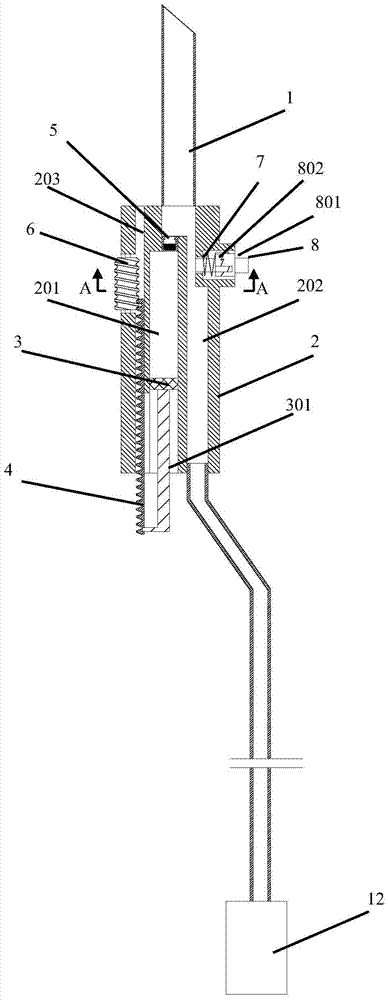
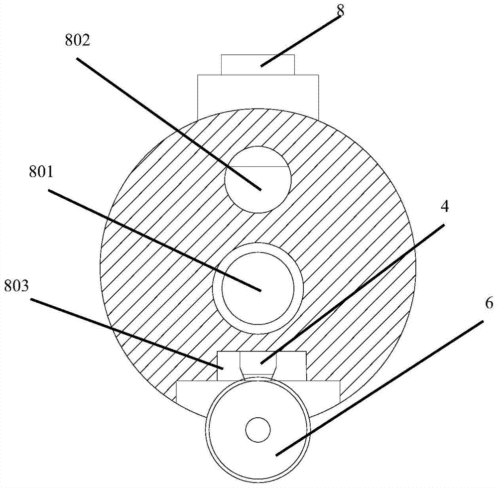
[0035] according to figure 1 , figure 2The illustrated thyroid puncture injection suction device includes a needle body 1 and a needle tube 2 , and the needle tube 2 has an injection channel 201 , a negative pressure suction channel 202 and a slideway 203 . The injection channel 201 is used to store injection fluid, a piston 3 is arranged in the injection channel 201 , and the tail end of the piston 3 is connected to a push handle 301 . The slideway 203 is close to the injection channel 201, and has an interface with the slideway 203 at the rear end of the injection channel 201. A sliding part 4 is installed in the slideway 203. The sliding part 4 is a rack, and the rack passes through the interface and the push handle 301 Connected, through the sliding part 4 moving in the slideway 203, the push handle 301 can be moved, thereby driving the piston 3 to move and push out the injection solution. There is a one-way valve 5 at the inlet of the injection channel 201, which is wh...

Embodiment 2

[0038] Such as image 3 The thyroid puncture injection suction device shown is the same as that in Embodiment 1, and a valve block 7 is set in the negative pressure suction channel 22, and the valve block 7 is connected to the button 8. Button 8 comprises briquetting block 803, left limit block 804 and right limit block 805, and briquetting block 803 bottom has slope, and valve block 7 top has slope, and left limit block 804 and right limit block 805 all have V-shaped slope. The lower part of the pressing block 803 abuts against the slopes of the upper parts of the left limiting block 804 and the right limiting block 805 , and the upper part of the valve block 7 abuts against the lower slopes of the left limiting block 804 and the right limiting block 805 . When the briquetting block 803 is pressed down, affected by the slope, the left limiting block 804 moves to the left, the right limiting block 805 moves to the right, and the valve block 7 moves downward to block the negati...


PUM


Abstract

The invention relates to a thyroid puncture injection suction device, which comprises a needle tube and a needle body installed at the front end of the needle tube. The needle tube has an injection channel and a negative pressure suction channel, and the injection channel and the negative pressure suction channel are connected to the needle body. The channel is connected; the injection channel is provided with a piston, the end of the piston is connected to the push handle, and a one-way valve is installed at the entrance of the injection channel; there is a valve block on the negative pressure suction channel, and there is a valve block on the needle wall. The negative pressure suction channel communicates with the through hole, and the valve block is connected with a button, and the button controls the sliding of the valve block up and down in the through hole. The beneficial effects of the present invention can realize injection and suction behaviors on one needle tube, and have little influence on the position of the needle tip, so that the operation is simple after the puncture is in place, and the injection point deviation and accidental damage caused by the displacement of the needle point caused by hand-handed operation are avoided.

Description

technical field [0001] The invention relates to the field of medical devices, in particular to a puncture and suction device for pathological diagnosis and ablation treatment of thyroid nodules. Background technique [0002] For thyroid nodules and cysts, puncture must be used to diagnose pathological specimens obtained by puncture of thyroid nodules, or to extract cyst fluid for treatment, so thyroid puncture needle is an important medical equipment. Under normal circumstances, the medical staff first use the B-ultrasound to guide the puncture. After the puncture is in place, they need to turn their hands to complete the injection. After the injection is completed, they use the suction auxiliary device to extract the cystic fluid. Since the three types of equipment need to be used alternately, the operation is more accurate. Decline and prone to injection point deviation and side injuries. [0003] The patent number is "CN104665896 A", the application number is "2013106137...

Claims


Application Information

Patent Timeline
IPC IPC(8): A61B10/02A61B17/34A61M5/178A61M1/00
Inventor 张浩刘胜陈森林
Owner NO 411 HOSPITAL OF PLA
Learn More