[0006]The present invention includes improved devices and methods for performing PMR procedures. One device allows for improved preparation of PMR catheters used to inject a
drug or therapeutic substance into the
heart wall. One such device includes a PMR device distal region or hood disposed within the neck of a
vial for receiving the
drug. The
vial can be used to receive the
drug while the drug is being flushed through the PMR device and needle to prepare the PMR device for use. One
vial has a neck and
shoulder region for receiving and retaining the distal region of a PMR
injection device. A no-leak
gasket defines one wall of an inner cavity within one such vial.
[0007]The vial is preferably formed of a transparent or translucent material for observing the injection of the drug into the vial. In one embodiment, the vial cavity includes a drug-neutralizing agent. The agent allows the drug to be neutralized after receiving the drug. A neutralizing agent can provide improved safety, should the integrity of the vial be breached. The drug-neutralizing vial allows a biologically active drug to be flushed through the
catheter with the vial being disposed of in a normal
waste stream such as a wastebasket, rather than requiring special handling.
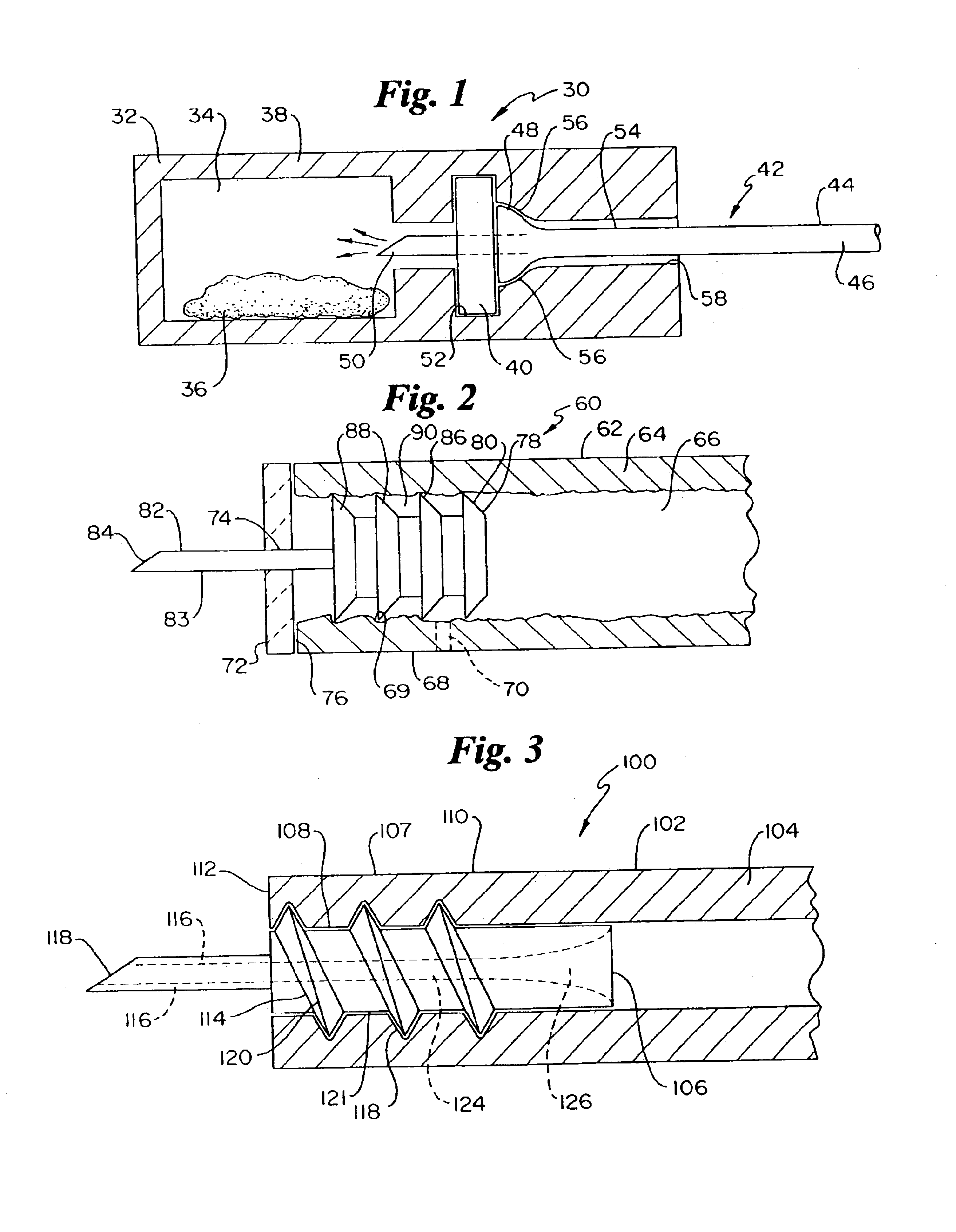
[0008]One set of devices provides improved needle attachment to
drug delivery tubes. One improved
drug delivery tube has an outer tube defining a lumen therein. A needle may be disposed within the distal end of the tube. The needle can have a distal, sharp tube region for
insertion into the
heart wall, as a well as a wider, more proximal region having outward protrusions for engaging or
biting into the
drug delivery tube inner wall. One device has a wide
flange for abutting the drug delivery tube distal end, thereby limiting the proximal travel of the needle into the drug delivery tube lumen. One drug delivery tube also has a bonding hole which can be used to inject an
adhesive to further secure the needle within the drug delivery tube distal region. The improved securing of the needle to the drug delivery tube can act to prevent the needle from being distally pulled from the tube.
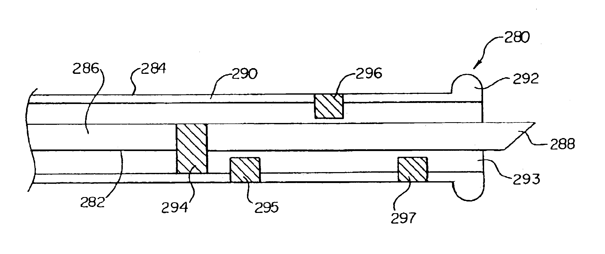
[0013]The present invention also includes a PMR device for allowing precise, variable depth
needle penetration of the heart wall. One device includes at least one inner stop affixed to a rotatable inner needle. The device also can have one or more stops disposed inwardly from an outer tube, the outer tube having the inner needle rotatably disposed within. The inner needle can be longitudinally advanced until the inner stop abuts an outer stop, thereby inhibiting further distal movement of the inner needle. If greater penetration is desired, the inner shaft can be rotated, thereby swinging the inner stop clear of the first encountered outer stop, allowing the inner stop to proceed further distally until a subsequent outer stop is encountered. This aspect of the invention allows a single device to be used, yet provides multiple, preset, precise penetration depths. This may be of particular use where the thickness of the heart wall varies over different regions of the
heart chamber wall.
[0014]Yet another aspect of the invention provides for injection of drug and contrast media into the heart wall. Injection of contrast media near the
injection site of a drug allows the treating physician to visualize under
fluoroscopy which areas of the heart wall have been treated and which have not yet been treated. One device provides a contrast media injection needle disposed side-by-side with a drug delivery needle. One embodiment allows the two side-by-side needles to be retracted and advanced together. The needles can be distally straight, arcuate, or one arcuate and one straight. Another embodiment provides a drug and contrast media
injection device having a pair of needles one being coaxially disposed within the other. The innermost needle can be used to inject drug deep into the heart tissue, while the more outer, coaxially disposed needle may be used to inject contrast media to the heart wall, thereby marking the site of treatment. One embodiment utilizes a sharp,
cutting end to inject contrast media. Another embodiment uses a less sharp, less
cutting end, for injecting a contrast media into the heart wall tissue using pressure, rather than
cutting.

