Solid catalyst hydrocarbon conversion process using stacked moving bed reactors

a technology of solid catalyst and moving bed reactor, which is applied in the direction of hydrocarbon oil cracking, catalytic naphtha reforming, organic chemistry, etc., can solve the problems of increasing the capital and operating costs of the process, requiring frequent regeneration, and relatively quick deactivation times of solid alkylation catalysts

Inactive Publication Date: 2011-06-23
UOP LLC
View PDF6 Cites 34 Cited by
  • Summary
  • Abstract
  • Description
  • Claims
  • Application Information

AI Technical Summary

Benefits of technology

[0023]In each aspect, the hydrocarbon feed stream can include one or more hydrocarbons, and an optional second feed stream can include another hydrocarbon or other reactant. Additionally, the plurality of liquid phase moving bed reactors can include a first moving bed reactor including a first outer annulus, a first centerpipe having a first centerpipe outlet, and a first reaction zone containing catalyst; and a second moving bed reactor including a second outer annulus, a second centerpipe having a first centerpipe outlet, and a second reaction zone containing catalyst. The first reactor feed stream can be received by the first outer annulus of the first moving bed reactor, can flow inward through the first reaction zone towards the first centerpipe, and can undergo a hydrocarbon conversion reaction in the first reaction zone to produce a first reactor e

Problems solved by technology

However, solid alkylation catalysts tend to have relatively quick deactivation times (e.g., about 2-24 hours) and require frequent regeneration.
For solid catalyst alkylation, higher internal I/O ratios will result in longer catalyst lives and an improved product quality, but will also increase the capital and operating costs of the process.
While not intending to be limited by theory, under some hydroprocessing conditions the hydrogen supply available at the catalytic reaction site may be a rate limiting factor in the hydroprocessing conversions.
The rapid reaction rate of the sulfur compounds to hydrogen sulfide will tend to consume hydrogen that is available within the catalyst pore structure thus limiting the amount of hydrogen available for other desired reactions, such as denitrogenation.
Under such circumstances with the rapid reaction rate of sulfur compounds, for example, it is believed that the amount of hydrogen available at the active catalyst sites can be limited by the diffusion of the hydrogen through the feed (especially at the initial portions of the reactor).
In these c

Method used


Image

  • Solid catalyst hydrocarbon conversion process using stacked moving bed reactors
  • Solid catalyst hydrocarbon conversion process using stacked moving bed reactors
  • Solid catalyst hydrocarbon conversion process using stacked moving bed reactors

Examples


Embodiment Construction

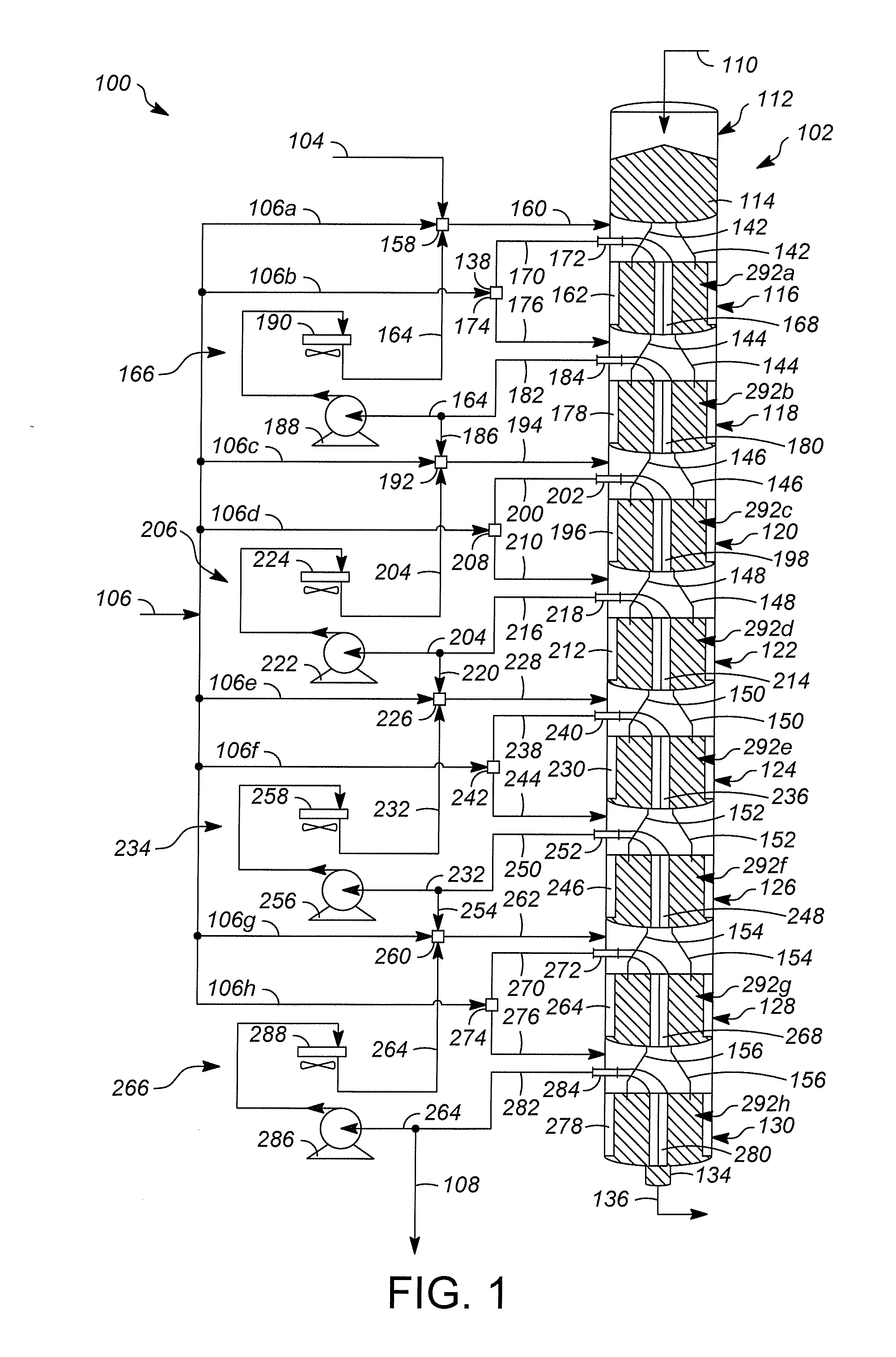
[0028]FIG. 1 illustrates one example of a hydrocarbon conversion system, illustrated generally at 100. Hydrocarbon conversion system 100 is a solid catalyst hydrocarbon conversion process operated in the liquid phase. Hydrocarbon conversion processes are well known in the art and include processes such as cracking, hydrocracking, alkylation of aromatics, alkylation of isoparaffins, isomerization, polymerization, reforming, dewaxing, hydrogenation, dehydrogenation, transalkylation, dealkylation, hydration, dehydration, hydrotreating, hydrodenitrogenation, hydrodesulfurization, and ring opening processes. Many of these processes are known to be successful when operated in the liquid phase mode.

[0029]An example of one class of liquid phase hydrocarbon conversion processes is olefin alkylation. In such an alkylation process, isobutene reacts with an acid site to form a tertiary carbenium ion (tC4+). The tC4+ ion reacts with an olefin molecule (C4═) to form a larger tertiary carbenium io...


PUM


Abstract

Systems and processes for hydrocarbon conversion are provided that utilize a plurality of moving bed reactors. The reactors may be moving bed radial flow reactors. Optional mixers that mix a portion of a second hydrocarbon feed with the effluent stream from an upstream reactor, to produce reactor feed streams may be employed, and the reactor feed streams may be introduced at injection points prior to each reactor. Catalyst can be provided from the reaction zone of one reactor to the reaction zone of a downstream reactor through catalyst transfer pipes, and can be regenerated after passing through the reaction zones of the reactors. The moving bed reactors can be stacked in one or more reactor stacks.

Description

CROSS REFERENCE TO RELATED APPLICATION[0001]This application claims the benefit of priority of U.S. Provisional Application 61 / 287,287, filed Dec. 17, 2009, the contents of which are hereby incorporated by reference in its entirety.FIELD OF THE INVENTION[0002]The systems and processes described herein relate to liquid phase hydrocarbon conversion processes utilizing a solid catalyst in a moving bed mode. The moving bed mode may be radial flow moving beds. The systems and processes described herein can be utilized, for example, for alkylation of hydrocarbons such as aromatics or paraffins to produce useful chemicals and motor fuel.BACKGROUND OF THE INVENTION[0003]The invention may be applied to a variety of different hydrocarbon conversion reactions. Some of these reactions may be described in simple terms such as A+B→C+D; or E→F; or G→H+I; or J+K→L. Additional reactants may be used or additional products may be generated depending upon the specific reaction. However, to benefit from...

Claims


Application Information

Patent Timeline
IPC IPC(8): C07C2/00
CPCC07C2/58C07C9/16
Inventor SADLER, CLAYTON C.WIER, MARY JOSTINE, LAURENCE O.NAUNHEIMER, CHRISTOPHER
Owner UOP LLC
Why Eureka
Try Eureka