
Punching die with auxiliary punching mechanism

A technology of punching die and elastic mechanism, which is applied in the direction of manufacturing tools, perforating tools, feeding devices, etc., can solve the problems of inaccurate hole positions, affecting production work, and circular pipe deviation, so as to improve the strength and rigidity, improve the The effect of improving the service life and work efficiency

Active Publication Date: 2016-01-06
重庆添棋汽车零部件有限公司
View PDF8 Cites 6 Cited by
  • Summary
  • Abstract
  • Description
  • Claims
  • Application Information

AI Technical Summary

Problems solved by technology

[0002] In the field of mechanical processing, it is often necessary to process holes on the side wall of the round tube. The traditional processing methods are mostly processed by drilling or milling. These processing methods are too inefficient to meet the needs of modern production.
[0003] In recent years, some punching dies have appeared, which can punch holes on the side wall of the round tube, but the structural design of these punching dies is not reasonable enough, resulting in the possibility of deviation of the round tube during the punching process, and the upper punch often has dimensions Smaller, bending may occur during the rapid punching process, resulting in inaccurate punched holes, and prone to scratches on the surface of the round tube, and even more serious may even cause the upper punch to break, seriously affecting the normal production work

Method used


Image

  • Punching die with auxiliary punching mechanism
  • Punching die with auxiliary punching mechanism
  • Punching die with auxiliary punching mechanism

Examples


Embodiment 1

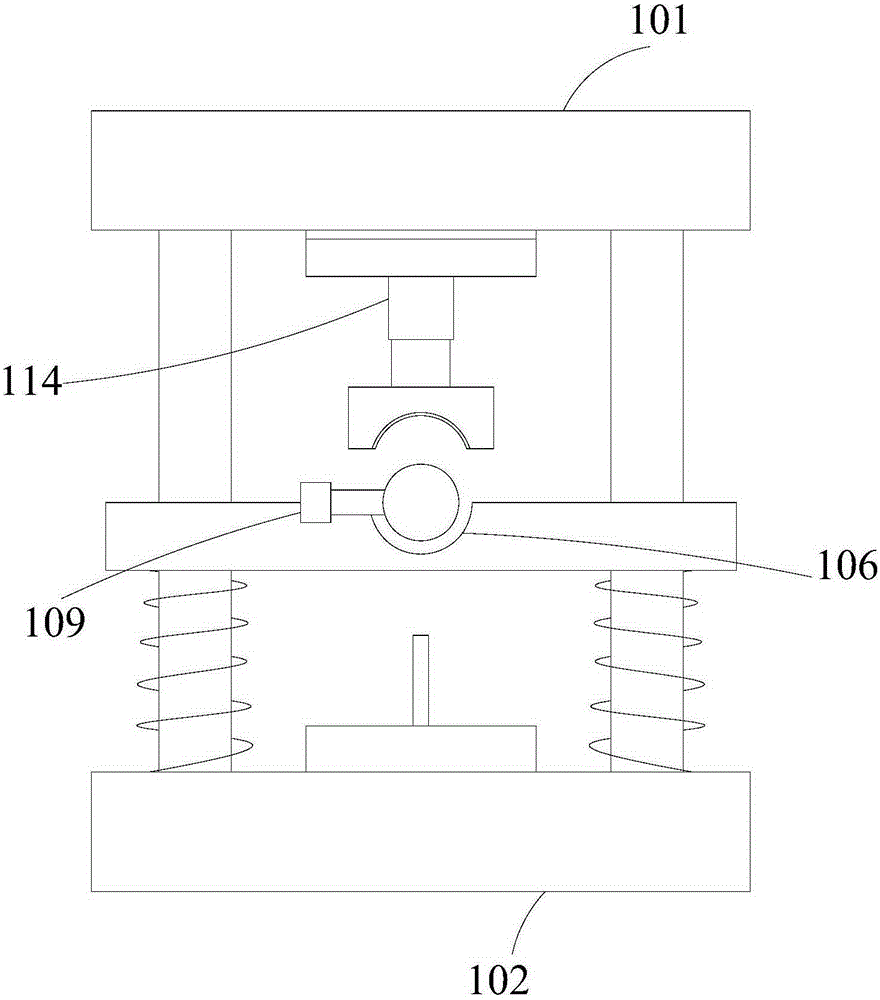
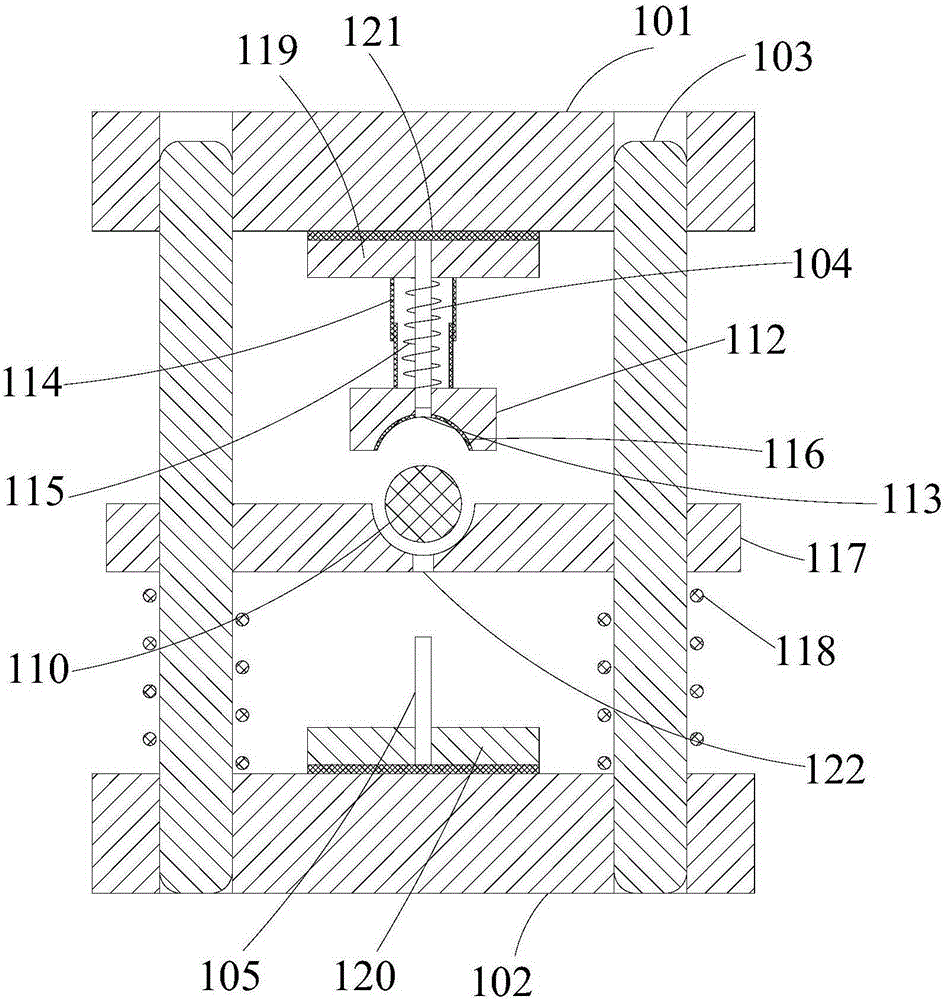
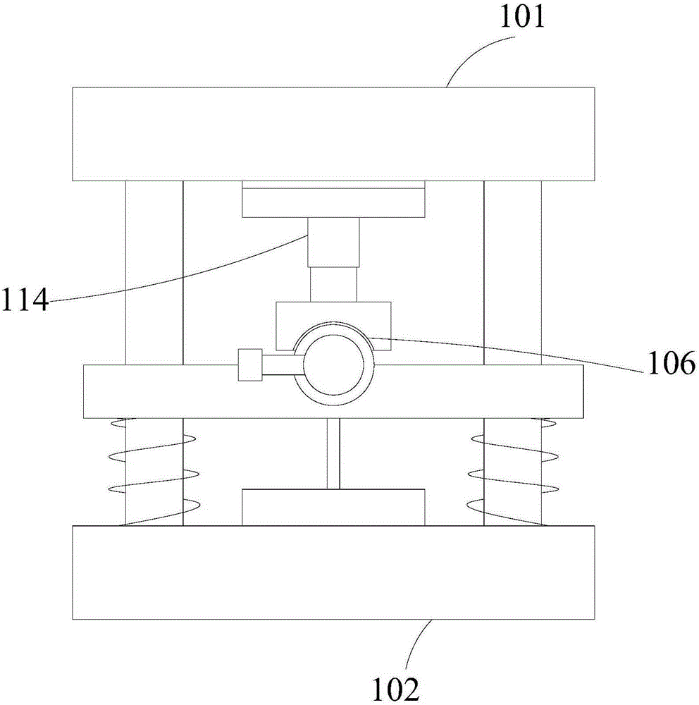
[0077] A punching die with an auxiliary punching mechanism, comprising an upper die base 101 and a lower die base 102, the upper die base 101 and the lower die base 102 are connected by a guide post 103, and an upper punch is connected to the bottom of the upper die base 101 104, the lower mold base 102 is longitudinally provided with a circular tube placement part 106; the outside of the upper punch 104 is provided with an auxiliary punching mechanism, the auxiliary punching mechanism includes a positioning block 112, the bottom surface of the positioning block 112 is a tensile structure, The outline of its bottom surface in the longitudinal section of the positioning block 112 is an arc, and the positioning block 112 is provided with a vertical through hole 113, and the upper punch 104 passes through the through hole 113; 101, the elastic mechanism enables the positioning block 112 to move in the vertical direction.

[0078] The elastic mechanism includes a sleeve assembly 1...


PUM


Abstract

The invention provides a punching die with an auxiliary punching mechanism and belongs to the field of dies. The punching die comprises an upper die base and a lower die base, wherein the upper die base and the lower die base are connected through a guide pillar, an upper male die body is connected to the bottom of the upper die base, and a round tube accommodating part is arranged on the lower die base in the longitudinal direction; the auxiliary punching mechanism is arranged outside the upper male die body and comprises a positioning block, the bottom surface of the positioning block is of a tensile structure, the contour line of the bottom surface of the interior of the longitudinal section of the positioning block is an arc, a vertical through hole is formed in the positioning block, and the upper male die body penetrates through the through hole; the positioning block is connected with the upper die base through an elastic mechanism, and the positioning block can move in the vertical direction through the elastic mechanism. By the adoption of the punching die, a round tube is more stable during punching, the upper male die body operates more smoothly, failures, such as bending, of the upper male die body are avoided, and the operation stability of the punching die is improved.

Description

technical field [0001] The invention relates to the field of molds, in particular to a punching die with an auxiliary punching mechanism. Background technique [0002] In the field of mechanical processing, it is often necessary to process holes on the side wall of the round tube. The traditional processing methods are mostly processed by drilling or milling. These processing methods are too inefficient to meet the needs of modern production. [0003] In recent years, some punching dies have appeared, which can punch holes on the side wall of the round tube, but the structural design of these punching dies is not reasonable enough, resulting in the possibility of deviation of the round tube during the punching process, and the upper punch often has dimensions Smaller, bending may occur during the rapid punching process, resulting in inaccurate punched holes, and prone to scratches on the surface of the round tube, and even more serious may even cause the upper punch to break...

Claims


Application Information

Patent Timeline
IPC IPC(8): B21D28/28B21D28/34B21D43/00
Inventor 杨静
Owner 重庆添棋汽车零部件有限公司
Learn More