Machining and positioning mechanism for corrugated faces of automotive gear shift oscillating bars

A technology of positioning mechanism and corrugated surface, which is applied in the direction of metal processing machinery parts, positioning devices, metal processing equipment, etc., can solve the problems of unguaranteed clamping reliability, decreased precision of corrugated surface, and low clamping efficiency, etc., to achieve Easy quality control, easy assembly, and high clamping efficiency

Inactive Publication Date: 2016-01-06
CHONGQING YIQUAN TECH CO LTD
View PDF6 Cites 0 Cited by
  • Summary
  • Abstract
  • Description
  • Claims
  • Application Information

AI Technical Summary

Problems solved by technology

The existing clamping device has a complex structure and a large volume, which is not only difficult to assemble, but also has high production costs, and the clamping operation is cumbersome, the clamping efficiency is not high, and the clamping reliability is not guaranteed; at the same time, only one piece can be processed at a time Workpieces, the processing efficiency is extremely low, and the milling cutter is easy to wear. With the increase of the number of processed workpieces, the accuracy of the corrugated surface processed by subsequent milling will decrease, and the processing quality will decrease.

Method used


Image

  • Machining and positioning mechanism for corrugated faces of automotive gear shift oscillating bars
  • Machining and positioning mechanism for corrugated faces of automotive gear shift oscillating bars
  • Machining and positioning mechanism for corrugated faces of automotive gear shift oscillating bars

Examples


Embodiment Construction

[0014] Below in conjunction with accompanying drawing and embodiment the present invention will be further described:

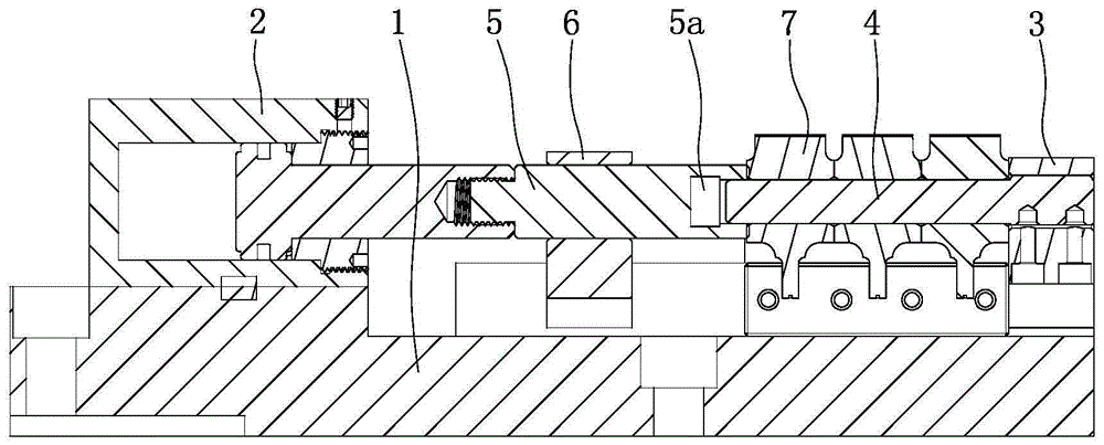
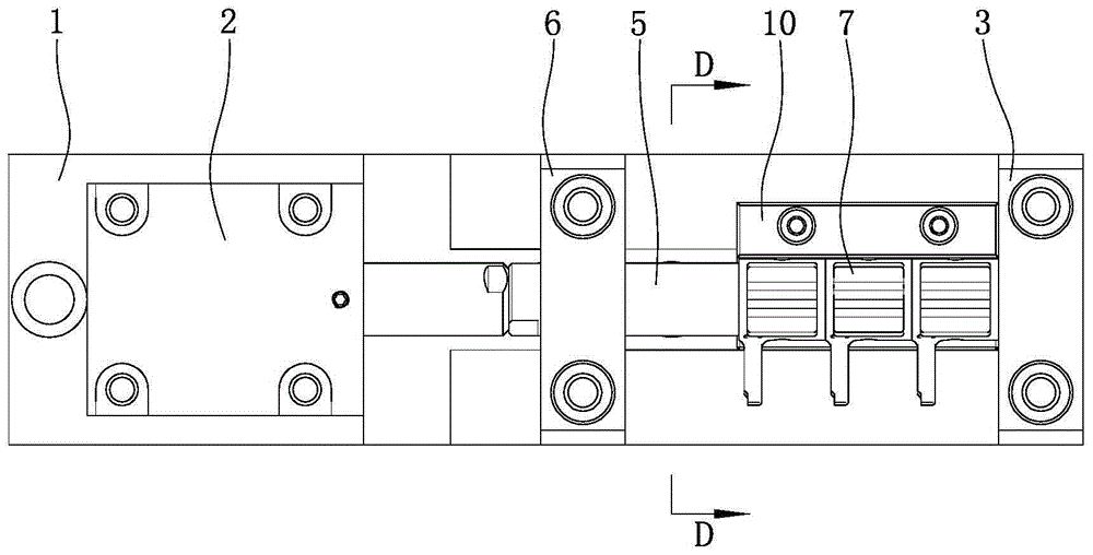
[0015] Such as figure 1 , figure 2 , image 3 As shown, the present invention is made of base 1, jacking oil cylinder 2, positioning seat 3, guide post 4, connecting rod 5 and guide seat 6 etc. Wherein, a jacking oil cylinder 2 is installed at the left end of the top of the base 1, and the piston rod of the jacking oil cylinder 2 stretches out horizontally to the right. Install the positioning seat 3 on the right end of the top of the base 1. The positioning seat 3 is a block body. The bottom end of the positioning seat 3 is embedded in the first matching groove on the base 1. The positioning seat 3 passes through two bolts from top to bottom. Fixed with base 1.

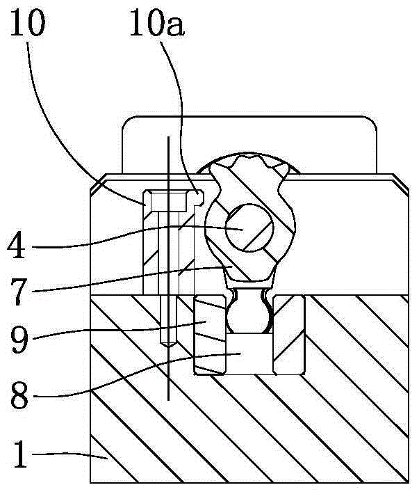
[0016] Such as figure 1 , figure 2 , image 3 As shown, a guide post 4 is provided on the positioning seat 3, and the guide post 4 is a cylinder and is located on a horizontal plane. The r...


PUM


Abstract

The invention discloses a machining and positioning mechanism for the corrugated faces of automotive gear shift oscillating bars. A connection rod is arranged between a guide column and a jacking oil cylinder and penetrates a guide seat. The base is provided with a positioning groove extending in the left-right direction. The positioning groove is located below the guide column. A front clamping strip and a rear clamping strip are arranged in the positioning groove, fixed to the base through bolts and arranged in parallel. The rear side of the guide column is provided with a limiting block in a long strip shape. The bottom face of the limiting block is attached to the top face of the base. The limiting block is fixed to the base through a row of bolts. The top of the front end face of the limiting block is integrally provided with a protruding edge extending in the left-right direction. According to the machining and positioning mechanism, the multiple gear shift oscillating bars are positioned precisely through cooperation of the connection rod and a positioning seat, the clamping firmness of the gear shift oscillating bars is good, and the machining efficiency and the machining accuracy of the corrugated faces of the gear shift oscillating bars are improved.

Description

technical field [0001] The invention relates to a wave surface processing and positioning mechanism of an automobile gear shift lever, which is used for clamping the gear shift lever to process the wave surface. Background technique [0002] The shift lever is an important part of the car gearbox. The existing shift lever is generally a steel forging, which is composed of a shaft sleeve, a ball head, a leg and a corrugated surface. There are pin holes, and the female and female pins are passed through the pin holes, so that the bushing and the shaft are fixed. The wave surface of the gearshift lever needs to be further processed on a milling machine, and the gearshift lever must be positioned on the milling machine with the aid of a specially made clamping device. The existing clamping device has a complex structure and a large volume, which is not only difficult to assemble, but also has high production costs, and the clamping operation is cumbersome, the clamping efficie...

Claims


Application Information

Patent Timeline
Patent Type & Authority Applications(China)
IPC IPC(8): B23Q3/08
CPCB23Q3/082B23C2215/08B23Q2703/04
Inventor 王咏真
Owner CHONGQING YIQUAN TECH CO LTD
Why Eureka
Try Eureka