Operation control method for multifunctional pedal

An operation control and multi-function technology, applied in the layout, transportation and packaging of control devices and power plant control mechanisms, can solve the problems of easy confusion between the accelerator pedal and the brake pedal, increased braking distance, and cumbersome operation. The effect of reducing body and foot fatigue, shortening the braking distance, and shortening the reaction time

Inactive Publication Date: 2016-01-06
王治平
View PDF5 Cites 2 Cited by
  • Summary
  • Abstract
  • Description
  • Claims
  • Application Information

AI Technical Summary

Problems solved by technology

[0002] At present, automobiles use three different pedals to control the accelerator, brake, and clutch, but they all use the pedal as the signal output condition. In actual control, misoperation often occurs, especially the accelerator pedal and the brake pedal are easily confused.
In addition, the current operation method of simultaneously controlling the two pedals of the brake and the accelerator with the right foot takes some time to switch between the accelerator and the brake. When driving at high speed, the braking distance will be significantly increased due to the difference in the switching speed of the driver.
In addition, the peripherals currently used in car driving games are mostly based on the current car pedals, using two or three pedals that can only be controlled by stepping on them, and there are similar shortcomings to those mentioned above during the game.
In any other equipment that needs to be controlled by stepping on the pedal, such as machine tools, electric sewing machines, etc., if it is necessary to use the pedal to control multiple functions, it also needs to be equipped with two or more pedals, and the control needs to be switched during the period. It also has the disadvantages of being confusing, cumbersome and time-consuming

Method used


Image

  • Operation control method for multifunctional pedal
  • Operation control method for multifunctional pedal
  • Operation control method for multifunctional pedal

Examples


Embodiment Construction

[0023] The present invention utilizes a controller and uses different actions to distinguish different specific input signals. The switching between different specific input signals is fast and not easy to confuse, which can improve the driving experience and driving safety of the car, and especially prevent the confusion of accelerator and brake. , and other control functions can be integrated on the pedal to achieve the purpose of more convenient operation.

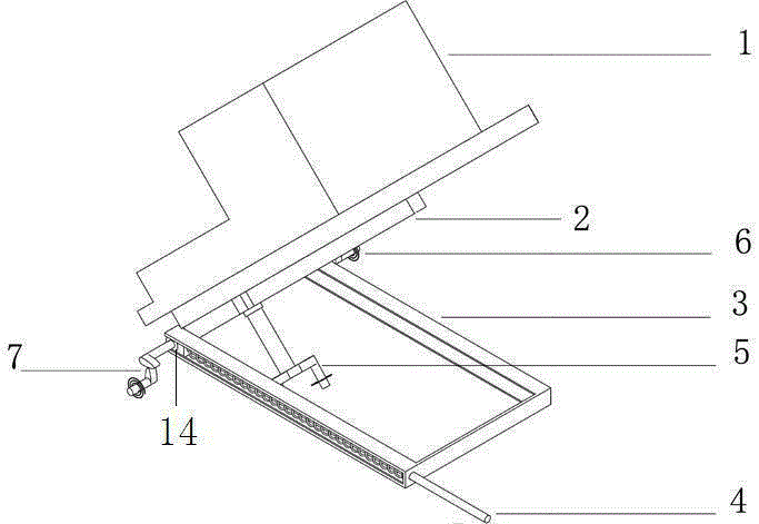
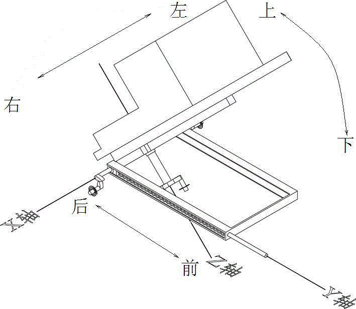
[0024] Take the static state when the pedal is not working as the reference coordinate, take the X axis as the rotation axis, set the specific input signal set by stepping on the pedal as X1, and set the specific input signal set by lifting the pedal as X2; use the Z axis as the rotation axis The specific input signal for clockwise rotation is set to Z1, the specific input signal for left-hand rotation is Z2; the specific input signal for pushing forward along the Y axis is Y1, and the specific input signal for backward ...


PUM


Abstract

The invention relates to an operation control method for a multifunctional pedal. According to the operation control method, the pedal is arranged to move in a plurality of directions; the coordinates of the pedal in a stationary state are taken as reference coordinates; the pedal is capable of moving in an up-and-down direction or independently moving upwards or downwards from the reference coordinates; the pedal is further capable of moving in at least one of left, right, front and back four directions; a control system sets an action of the pedal moving in a specific direction away from the reference coordinates as a specific input signal; each specific input signal corresponds to a specific operation action; when the pedal moves in a corresponding direction away from the reference coordinates, the control system receives the specific input signal and realizes specific corresponding operation control according to the received specific input signal; correspondingly, the control system controls a corresponding component according to each specific input signal so that the corresponding component operates to perform the corresponding action. The operation control method for the multifunctional pedal is simple in design and low in cost, and thus is convenient for control in such a manner of outputting different signals through different operations.

Description

technical field [0001] The invention belongs to a multifunctional pedal, and in particular relates to realizing different signal outputs on a pedal by adopting different actions. Background technique [0002] At present, automobiles use three different pedals to control the accelerator, brake, and clutch, but they all use the pedal as the signal output condition. In actual control, misoperation often occurs, especially the accelerator pedal and the brake pedal are easily confused. In addition, the current operation method of simultaneously controlling the two pedals of the brake and the accelerator with the right foot takes some time to switch between the accelerator and the brake. When driving at high speed, the braking distance will be significantly increased due to the difference in the switching speed of the driver. In addition, the peripherals currently used in car driving games are mostly based on the current car pedals, using two or three pedals that can only be contr...

Claims


Application Information

Patent Timeline
Patent Type & Authority Applications(China)
IPC IPC(8): B60K26/02B60K23/02B60T7/06
Inventor 王治平
Owner 王治平
Why Eureka
Try Eureka