Industrial vehicle travel control device and method
A technology for driving control and industrial vehicles, which is applied in the direction of control devices, vehicle accessories, vehicle parts, etc., and can solve the problems of operating handle restrictions, etc., and achieve the effects of improving comfort, simple structure, and convenient maintenance
- Summary
- Abstract
- Description
- Claims
- Application Information
AI Technical Summary
Problems solved by technology
Method used
Image

Examples
Embodiment 1
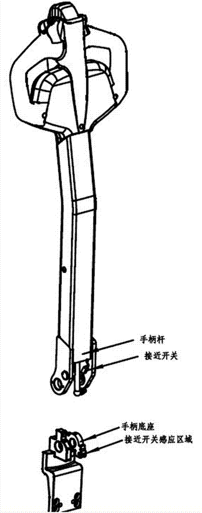
[0039] Such as Figure 4 As shown, the operating handle 1 includes a handle rod 11 and a handle base 12 . The handle base 12 is vertically provided with mounting plates 121 parallel to each other, and a rotating shaft 122 is fixedly installed between the mounting plates 121 through elastic pins 1211 . One end of the handle rod 11 is provided with a connecting plate 111 parallel to the mounting plate 121 and docked with the mounting plate 121 . A through hole 112 is provided on the connecting plate 111 corresponding to the position of the rotating shaft 122 , so that the rotating shaft 122 is rotatably connected to the handle bar 11 through the through hole 112 . The other end of the handle bar is fixedly connected to the handle head 13. The handle bar 11 swings in a vertical plane with the rotating shaft 122 as the axis. A magnetic sensitive component 1221 is disposed at one end of the rotating shaft 122 , and a Hall element 1121 is disposed outside the through hole 112 of ...
Embodiment 2
[0042] The industrial vehicle travel control device described in the second embodiment has many similarities with the first embodiment. For the sake of brevity, this embodiment focuses on the differences. For the similarities, please refer to the description of the first embodiment.
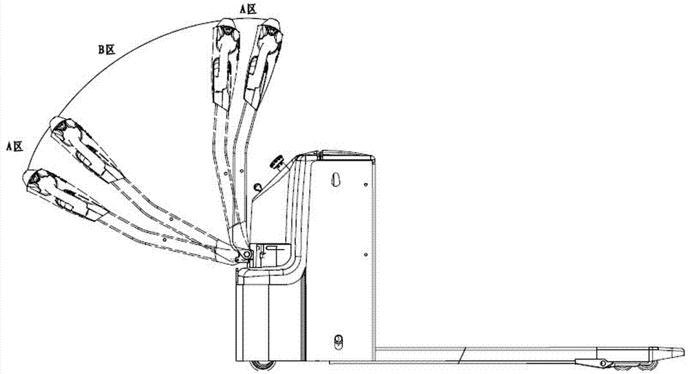
[0043] When the minimum speed at which the vehicle is driven by the fast state area 31 is far greater than the fastest speed at which the vehicle is driven by the slow state area 33 . In order to prevent the speed difference between the fast speed and the slow speed of the vehicle from being too large, resulting in a sudden change in the speed of the vehicle when switching between the fast state area and the slow state area, causing discomfort to the operator; at the same time, reducing safety accidents caused by misoperation risks of. Embodiment 2 A transition state area 34 is set between the fast state area 32 and the slow state area 33 . The speed at which the vehicle is driven by the transit...
Embodiment 3
[0046] The industrial vehicle driving control device described in the third embodiment has many similarities with the first embodiment. For the sake of brevity, this embodiment focuses on the differences. For the similarities, please refer to the description of the second embodiment.
[0047] The positions of the Hall element and the magnetic-sensing component in Embodiment 1 are reversed, the Hall element is arranged at one end of the rotating shaft, and the magnetic-sensing component is arranged outside the through hole of the connecting plate, so that the Hall element is located inside the magnetic-sensing component and faces it.
PUM
 Abstract
Description
Claims
Application Information
 - R&D
- Intellectual Property
- Life Sciences
- Materials
- Tech Scout
- Unparalleled Data Quality
- Higher Quality Content
- 60% Fewer Hallucinations
Browse by: Latest US Patents, China's latest patents, Technical Efficacy Thesaurus, Application Domain, Technology Topic, Popular Technical Reports.
© 2025 PatSnap. All rights reserved.Legal|Privacy policy|Modern Slavery Act Transparency Statement|Sitemap|About US| Contact US: help@patsnap.com