
Air hose dehydration cabinet

A technology of water tanks and air ducts, which is applied to hull ventilation/heating/cooling, ship components, ships, etc. It can solve problems such as safety and life threats of navigation equipment, influence of ship structure, and difficult layout, so as to ensure ventilation reliability, The effect of great promotion value and convenient operation

Inactive Publication Date: 2016-01-06
CSSC HUANGPU WENCHONG SHIPBUILDING COMPANY
View PDF8 Cites 1 Cited by
  • Summary
  • Abstract
  • Description
  • Claims
  • Application Information

AI Technical Summary

Problems solved by technology

[0002] The ventilation pipes of the propulsion cabin, steering gear cabin and other rooms under the main deck of the ship are generally arranged on the main deck, and the sea conditions are complex and changeable, and the waves often beat up to the main deck or even higher places, which will cause the sea water to flow along the main deck. The ventilation pipe is blown into the room in the cabin by the fan, causing damage to various equipment in the room, thereby posing a greater threat to the safety and life of the navigation equipment, so this situation should be avoided as much as possible during the design and construction of the ship the emergence of
However, for ships built on the bow, it is very difficult to arrange the ventilation of the stern thruster compartment to the bow for ventilation. In the prior art, there is a method of increasing the height of the ventilator to solve the above problems, but for There are problems with the installation and maintenance of the ventilator. It is also very abrupt to set up a very high ventilator at the tail, which will affect other structures of the ship.

Method used


Image

  • Air hose dehydration cabinet
  • Air hose dehydration cabinet

Examples


Embodiment 1

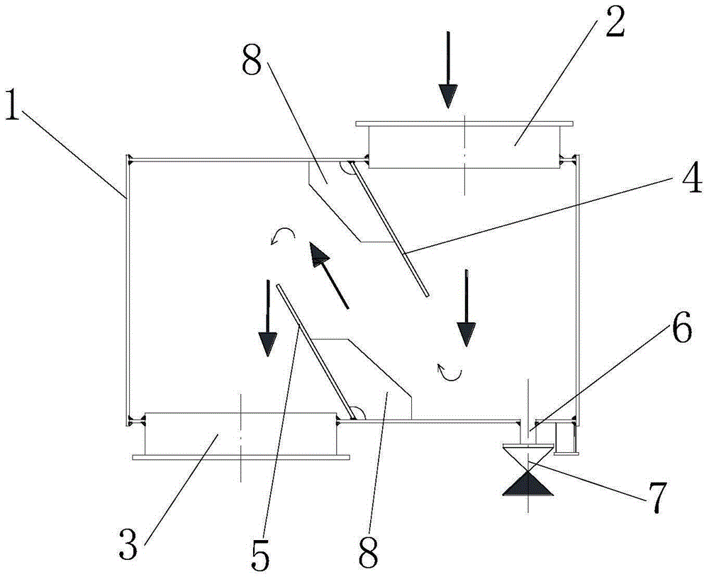
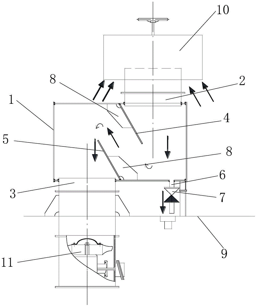
[0018] Such as figure 1 As shown, the air duct water removal cabinet of this embodiment includes a cabinet body 1, an air inlet port 2 is arranged on the top plate of the cabinet body 1, an air outlet port 3 is arranged on the bottom plate of the cabinet body 1, and the The air inlet interface 2 and the air outlet interface 3 are misplaced, and the inside of the cabinet body 1 is also provided with a wind guide and water removal device. The wind and water removal plate 5, the upper wind guide and water removal plate 4 and the lower wind and water removal plate 5 are arranged at a certain inclined angle between the wind interface and the air outlet interface 3, corresponding to the bottom plate at the air inlet interface 2 A drain port 6 is also provided, and a check valve 7 is arranged on the drain port 6. The present invention can effectively enable the air coming in from the air inlet port 2 to pass through the wind guide and dewatering device, and enter the cabin 11 through...


PUM


Abstract

The invention relates to the dehydration device technical field, and specifically relates to an air hose dehydration cabinet comprising a cabinet body; a top plate of the cabinet body is provided with air inlet interface; the bottom plate of the cabinet body is provided with an air outlet interface; the air inlet interface and the air outlet interface are offset; an air guide dehydration device is also arranged in the cabinet body, and comprises an upper air guide dehydration plate and a lower air guide dehydration plate mutually interlaced; the upper and lower air guide dehydration plates are arranged between the air inlet interface and the air outlet interface in certain oblique angle; the bottom plate is also provided with a water discharge port matched with the air inlet interface; the water discharge port is provided with an inverted valve, so the air from the air inlet interface can penetrate the air guide dehydration device, and enters a cabin through the air outlet interface; sea water from the air inlet interface can be blocked by the air guide dehydration device, and discharged by the water discharge port, thus effectively preventing sea water from entering the cabin through the air hose, reducing air hose height, and the equipment in the cabin cannot damaged by water.

Description

technical field [0001] The invention relates to the technical field of water removal devices, in particular to an air duct water removal cabinet for preventing seawater from entering a cabin through an air duct. Background technique [0002] The ventilation pipes of the propulsion cabin, steering gear cabin and other rooms under the main deck of the ship are generally arranged on the main deck, and the sea conditions are complex and changeable, and the waves often beat up to the main deck or even higher places, which will cause the sea water to flow along the main deck. The ventilation pipe is blown into the room in the cabin by the fan, causing damage to various equipment in the room, thereby posing a greater threat to the safety and life of the navigation equipment, so this situation should be avoided as much as possible during the design and construction of the ship appear. However, for ships built on the bow, it is very difficult to arrange the ventilation of the stern ...

Claims


Application Information

Patent Timeline
Patent Type & Authority Applications(China)
IPC IPC(8): B63J2/10
Inventor 彭秀清
Owner CSSC HUANGPU WENCHONG SHIPBUILDING COMPANY
Learn More