Corner lift for sliding plates

A lift, skateboard technology, applied in the direction of lifting device, etc., can solve the problem that the number of occupied stations affects the utilization rate of the workshop, etc., and achieves the effects of convenient and fast installation, low production cost, and reliable and stable operation of the mechanism.

Inactive Publication Date: 2016-01-06
MH ROBOT & AUTOMATION
7 Cites 2 Cited by

AI-Extracted Technical Summary

Problems solved by technology

[0002] In the automobile assembly production line, the skateboard line is a widely used assembly conveyor line. At present, the skateboard production line needs to change the height of ...

Abstract

The invention discloses a corner lift for sliding plates. The corner lift comprises a lifting system, a turning track system, a friction driving system and a sliding plate alignment locking device. The lifting system is composed of a driving platform, four hollow round pipe guiding stand columns, speed reducers, main driving shafts, driving chains, a lifting frame and balance weight devices. The driving platform on the tops of the guiding stand columns is provided with driving chain wheels corresponding to the guiding stand columns respectively. The four driving chain wheels are driven through the two speed reducers respectively. The two corresponding driving chain wheels driven by the same speed reducer are in transmission connection through the corresponding main driving shaft. The driving chains are connected to guiding wheel devices at the four corners of the lifting frames respectively and pass through the corresponding driving chain wheels, and the other ends of the driving chains are connected with the balance weight devices arranged in the four guiding stand columns respectively. Compared with the mode that a lift and a turning table are used in a combined manner at present, the corner lift for the sliding plates has the beneficial effects of being compact in structure and capable of reducing the occupied area.

Application Domain

Technology Topic

Image

  • Corner lift for sliding plates
  • Corner lift for sliding plates
  • Corner lift for sliding plates

Examples

  • Experimental program(1)

Example Embodiment

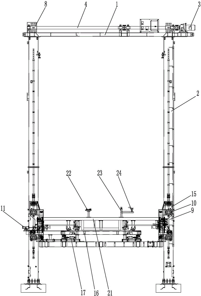
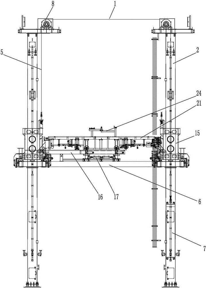
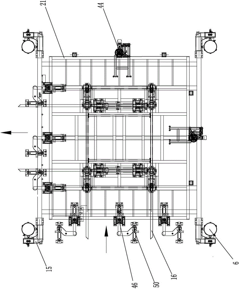
[0033] Such as Figure 1-11 As shown, the skateboard corner elevator includes a lifting system, a direction-changing track system, a friction drive system, and a skateboard alignment locking device 11;
[0034] The lifting system consists of a driving platform 1, four hollow circular tube guide columns 2, a reducer 3, a driving spindle 4, a driving chain 5, a lifting frame 6, and a counterweight device 7. A horizontal driving platform is set on the top of the guide column 2 to lift The frame 6 is horizontally arranged between the four guide columns 2 through the guide wheel devices 15 provided on its four corners. The driving platform 1 on the top of the guide column 2 is respectively provided with driving sprockets 8 corresponding to the guide columns 2. The four driving The sprocket 8 is driven by two reducers 3 respectively, and the two drive sprockets 8 driven by the same reducer 3 are connected by a drive spindle 4, and the four corner guide wheel devices 15 on the lifting frame 6 are respectively connected with Drive chain 5, drive chain 5 passes through each corresponding drive sprocket 8, and the other end is respectively connected with the counterweight device 7 arranged inside the four guide columns 2; the guide wheel device 15 is composed of a guide wheel fixing plate 9 and a guide wheel 10. It is composed of four guide wheels 10, and each two guide wheels 10 form a clamping guide wheel group, which are respectively arranged on the upper and lower ends of the guide plate fixing plate 9, and are respectively clamped on the vertical track on the guide column 2; The weight device 7 is composed of a cylindrical counterweight cylinder 12, a counterweight support pulley 13, and a chain fixing plate 14. The upper and lower ends of the counterweight cylinder 12 are respectively provided with a plurality of counterweight support pulleys 13, and the counterweight support pulleys 13 are arranged around. On the outer edges of the upper and lower end surfaces of the counterweight cylinder 12, the counterweight cylinder 12 is in contact with the inner side wall of the guide column 2 through the counterweight support pulley 13, and the upper end of the counterweight cylinder 12 is provided with a chain fixing plate 14 fixedly connected with the drive chain 5 ;
[0035] The direction-changing track system consists of a well-shaped track device 16, a partial track pneumatic lifting device 17, and a track lifting guide device 18. The well-shaped track device 16 is set on the lifting frame 6 through the local track pneumatic lifting device 17, and the well-shaped track device The horizontal slide rail 19 and the longitudinal slide rail 20 of 16 respectively realize the lifting of each slide rail through a separate partial rail pneumatic lifting device 17, and the local rail pneumatic lifting device 17 is provided with a rail lifting guide device 18, and a well-shaped rail device 16 A skateboard 21 is provided on the skateboard 21, and a vehicle body support tool is provided on the skateboard 21. The vehicle body support tool is composed of a rear body support frame 22, a front body support frame 23, and a front wheel support frame 24. The front wheel support frame 24 is installed on the vehicle. The front body support frame 23; the bottom of the sliding plate 21 is provided with a left and right running wheel set 25 and a front and rear running wheel set 26 for support, and the left and right running wheel set 25 is located on the transverse slide 27 of the tic-tac-shaped track device 16, front and rear The running wheel set 26 is located on the longitudinal slide 28 of the well-shaped track device 16, the left and right running wheel sets 25 and the front and rear running wheel sets 26 at the bottom of the skateboard 21 are located on the same horizontal plane; the partial track pneumatic lifting device 17 is lifted by the slide rail swing 29. The inclined iron slider 30, the slider pushing pulley 31, the pulley pushing cylinder 32, and the pulley fixed slide 33 are composed of the horizontal slide rail 27 and the longitudinal slide rail 28 respectively set at one end of the slide rail swing lifting plate 29 corresponding to them. , The other end of the sliding rail swing lifting plate 29 is rotatably connected with the fixed frame 34, and the bottom of the sliding rail swing lifting plate 29 provided with one end of the sliding rail is provided with an inclined iron sliding block 30 facing downwards, and the inclined iron sliding block 30 The lower lifting frame 6 is provided with a fixed pulley slide 33, and a slidable slide block pushing pulley 31 is provided in the fixed pulley slide 33. The slide pushing pulley 31 contacts the inclined surface of the bottom of the inclined iron slide block 30, and the pulley pushes the cylinder 32. The push rod is rotatably connected with the sliding block pushing the pulley 31, and the other end is rotatably connected with the bottom of the fixed frame 34, so that the sliding block pushing pulley 31 can move on the fixed slide 33 of the pulley through the drive of the pulley pushing cylinder 32; the rail lifting guide device 18 is composed of a track guide fixing frame 35, a lifting guide plate 36, and a slide rail side plate 37. The track guide fixing frame 35 is respectively arranged on both sides of the horizontal slide rail 27 and the longitudinal slide rail 28, and the top of the track guide fixing frame 35 is respectively arranged Slide rail side plate 37, so that the horizontal slide rail 27 and the longitudinal slide rail 28 are respectively located between the two corresponding slide rail side plates 37, one end of the lifting guide plate 36 is rotatably connected with the rail guide fixing frame 35, and the other end is respectively connected with the corresponding The lateral slide rails 27 or the longitudinal slide rails 28 are rotatably connected.
[0036] The friction drive system consists of a front and rear running friction drive device and a left and right running friction drive device. The friction drive device 44 consists of a friction drive wheel 38, a sliding plate sensor 39, a friction drive wheel servo motor 40, a servo motor base 41, and a fixed rotating plate 42 of the machine base. , The motor compression cylinder 43 is composed of a friction drive wheel 38 arranged on the servo motor base 41, the friction drive wheel 38 is driven by the friction drive wheel servo motor 40 arranged on the servo motor base 41, and one end of the servo motor base 41 is fixed by the base The rotating plate 42 is rotatably connected with the friction system fixing plate 45, and the other end is rotatably connected with the friction system fixing plate 45 through the motor compression cylinder 43. A friction clamping device 46 is provided on the opposite side of each friction driving device 44 to cooperate with it. To realize the clamping drive and positioning of the sliding plate 21, the friction clamping device 46 is composed of a friction clamping wheel 47, a friction clamping wheel swing arm 48, and a clamping wheel swing cylinder 49. One end of the friction clamping wheel swing arm 48 is rotatably connected To the lifting frame 6, and rotatably connected with the clamping wheel swing cylinder 49, the friction clamping wheel swing arm 48 is realized through the clamping wheel swing cylinder 49, and the friction clamping wheel 47 is arranged on the friction clamping wheel swing arm 48 The other end is perpendicular to the friction clamping wheel swing arm 48; the lifting frame outside each friction clamping device is also provided with a locking device 50 corresponding to the friction clamping device 46, and the locking device 50 is locked The locking cylinder 51, the locking plate connecting plate 52, and the locking plate 53 are composed. One end of the locking plate connecting plate 52 is fixedly connected with the push rod of the locking cylinder 51, and the other end is fixedly connected with the locking plate 53 to make the locking plate 53 corresponds to the gap of the rotating end of the friction clamping wheel swing arm 48;
[0037] A total of four sets of slide plate alignment locking devices 11 are respectively located on the guide wheel device 15 of the lifting frame 6. The slide plate alignment locking device 11 is positioned by the latch cylinder 54, the latch cylinder fixing seat 55, the locking pin 56, and the locking pin. The pin cylinder 54 is set on the guide wheel device 15 through the pin cylinder fixing seat 55. The locking pin passes through the positioning seat 57 and the locking pin 56 penetrates horizontally. One end of the locking pin 56 is pushed by the pin cylinder 54 The rods are connected, and the other end corresponds to the positioning hole of each sliding plate 21.
[0038] The foregoing descriptions are only illustrative specific embodiments of the present invention, and are not used to limit the scope of the present invention. Any equivalent changes and modifications made by any person skilled in the art without departing from the concept and principle of the present invention shall fall within the protection scope of the present invention.

PUM

no PUM

Description & Claims & Application Information

We can also present the details of the Description, Claims and Application information to help users get a comprehensive understanding of the technical details of the patent, such as background art, summary of invention, brief description of drawings, description of embodiments, and other original content. On the other hand, users can also determine the specific scope of protection of the technology through the list of claims; as well as understand the changes in the life cycle of the technology with the presentation of the patent timeline. Login to view more.

Similar technology patents

Locking structure and paper box for printing on POS machine without buckle hand

PendingCN108086826ASimple structure and operationWing fastenersEngineeringMechanical engineering
Owner:SHENZHEN XINGUODU PAYMENT TECH CO LTD

Multifunctional electric vehicle charger

InactiveCN112290625ASimple structure and operationGood human-computer interfaceCircuit monitoring/indicationCharging stationsAutomotive engineeringElectric vehicle
Owner:天长市绿普尔电子有限公司

Classification and recommendation of technical efficacy words

  • Simple structure and operation
  • Easy to install

Rotary type vehicle carrying board one-position for two-car parking device

InactiveCN101033653AReduce channel areaSimple structure and operationParkingsElectric machineryVehicle frame
Owner:朱建华

Overturn-preventing falling-preventing attached lifting scaffold

InactiveCN105401715ASimple structure and operationBuilding support scaffoldsEngineeringSelf weight
Owner:ZHONGYIFENG CONSTR GRP

Puncture needle positioning device

ActiveCN106852702AImprove efficiency and accuracySimple structure and operationDiagnosticsSurgical needlesNeedle positionSurgery
Owner:METAL INDS RES & DEV CENT +1

Organic vacuum evaporation source

PendingCN106987809ASimple structure and operationEasy to produceVacuum evaporation coatingSputtering coatingPhysicsThermocouple Wire
Owner:DALIAN JIAOTONG UNIVERSITY

Ultrasound guidance system

InactiveUS20070073155A1Easy to installAccurate and simple needle placementUltrasonic/sonic/infrasonic diagnosticsSurgical needlesUltrasound guidanceNeedle guidance
Owner:ULTRASOUND VENTURES

Power train for small recreational vehicle

InactiveUS20050173180A1Easy to installRace vehiclesUnderstructuresTransaxleAutomotive engineering
Owner:TECUMSEH PROD CO
Why Eureka
Try Eureka