Self-suction airlift fermenting tank

An air-lift fermentation tank, self-priming technology, applied in the field of fermentation tanks, can solve the problems of unsatisfactory gas-liquid mixing effect, inability to rotate, and inability to apply high-viscosity material fermentation, etc., to achieve good gas-liquid mixing effect and simple structure , Good effect of gas-liquid mixing and dispersing performance

Active Publication Date: 2016-01-06
陆飞浩
View PDF5 Cites 12 Cited by
  • Summary
  • Abstract
  • Description
  • Claims
  • Application Information

AI Technical Summary

Problems solved by technology

This kind of fermentation tank has no stirring device, and the fermentation gas and liquid are mixed in a swirl state under the action of the swirl mixer, and circulate inside and outside along the flow guide device, but the swir

Method used


Image

  • Self-suction airlift fermenting tank
  • Self-suction airlift fermenting tank
  • Self-suction airlift fermenting tank

Examples


Embodiment Construction

[0018] The present invention will be further described in detail below in conjunction with the accompanying drawings and embodiments.

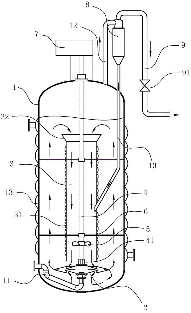
[0019] Such as Figure 1~3 As shown, the self-priming air-lift fermenter of the present embodiment includes a cylindrical tank body 1, an air intake device, an exhaust device, a flow guiding device, a cooling device, a stirring device and an air intake pipe arranged on the tank body 1 11. Exhaust pipe 12, the air intake pipe 11 is located at the bottom of the tank body 1 and connected with the air intake device, and the exhaust pipe 12 is located at the top of the tank body 1 and connected with the exhaust device.

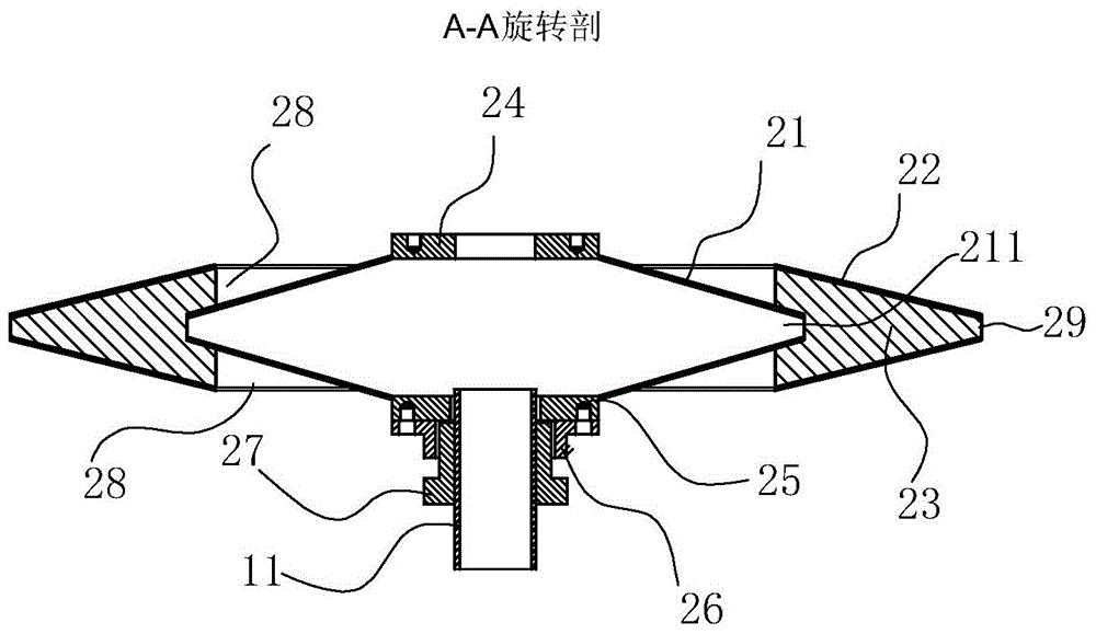
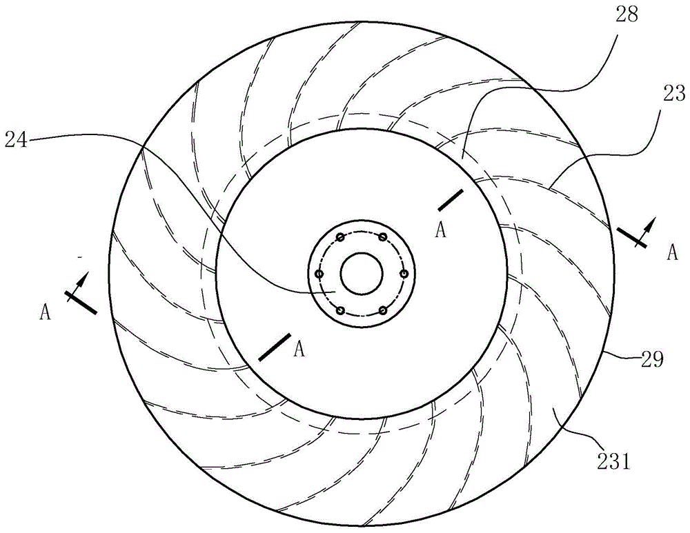
[0020] The air intake device is not a simple annular pipe with densely distributed small holes, nor a jet gas-liquid mixer, but a rotatable swirl mixer 2, which is located at the bottom of the tank body 1. The stirring device includes a stirring shaft 4 and a stirrer 5, the stirring shaft 4 is arranged on the axis of the tank body...


PUM


Abstract

A self-suction airlift fermenting tank comprises a tank body, an intake device, an exhaust device, a flow guide device, and an intake pipe and an exhaust pipe disposed on the tank body. The intake device is a cyclone mixer disposed at the bottom of the tank body and communicated with the intake pipe. The flow guide device is disposed in the tank above the cyclone mixer. The self-suction airlift fermenting tank is characterized in that the flow guide device is a flow guide barrel, the flow guide barrel is vertically disposed on the axis of the tank body, a stirring shaft with a stirrer is disposed on the axis of the tank body, the upper end of the stirring shaft is extended out of the tank body and connected with a motor, the lower end of the stirring shaft is connected with the cyclone mixer, and the stirrer is disposed on the lower portion of the inside of the flow guide barrel. The cyclone mixer rotates with rotating of the stirring shaft, liquid is imparted high kinetic energy by the aid of the rotating cyclone mixer, suction is generated when the liquid leaves, air sucked in may enter the fermenting tank under lower pressure, and air utilization can be increased. The self-suction airlift fermenting tank has the advantages of simple structure, good gas-liquid mixing effect and high fermenting efficiency and has significant comprehensive energy efficiency.

Description

technical field [0001] The invention relates to a fermenter, in particular to a self-priming air-lift fermenter used in large-scale industrial production as an aerobic microbial fermentation. Background technique [0002] Usually, the aerobic microbial fermentation tank has a stirring system, a cooling system, and a ventilation and exhaust device inside. With the continuous expansion of industrial mass production fermentation scale, the diameter and height of a single fermentation tank have also doubled. The diameter of the fermenter has increased from 2m to 4m in the past to the current 4m to 10m; the height has increased from the past 5m to 10m to the current 10m to 20m. Since the stirring power is proportional to the 5th power of the diameter of the stirrer, the stirring power doubles after the volume of the fermenter is enlarged, resulting in a substantial increase in energy consumption. At the same time, the static pressure of the liquid layer in the tank increases, a...

Claims


Application Information

Patent Timeline
IPC IPC(8): C12M1/04C12M1/02C12M1/00
Inventor 陆飞浩
Owner 陆飞浩
Why Eureka
Try Eureka