Upper lower adjustable clamp apparatus for sponge cutting mechanism

A sponge cutting and clamping device technology, applied in textiles, papermaking, textile material cutting, etc., can solve the problems of lower production efficiency, no device capable of cutting circles, troubles, etc., and achieve good results and convenient cutting

Active Publication Date: 2016-01-06
南通真馨家纺有限公司
View PDF6 Cites 13 Cited by
  • Summary
  • Abstract
  • Description
  • Claims
  • Application Information

AI Technical Summary

Problems solved by technology

[0002] At present, when making warm earmuffs, the interior needs to be filled with sponge, and the sponge needs to be cut into small circular shapes. The existing method is to cut it with manual scissors, which is very troublesome and greatly r

Method used


Image

  • Upper lower adjustable clamp apparatus for sponge cutting mechanism
  • Upper lower adjustable clamp apparatus for sponge cutting mechanism

Examples


Embodiment Construction

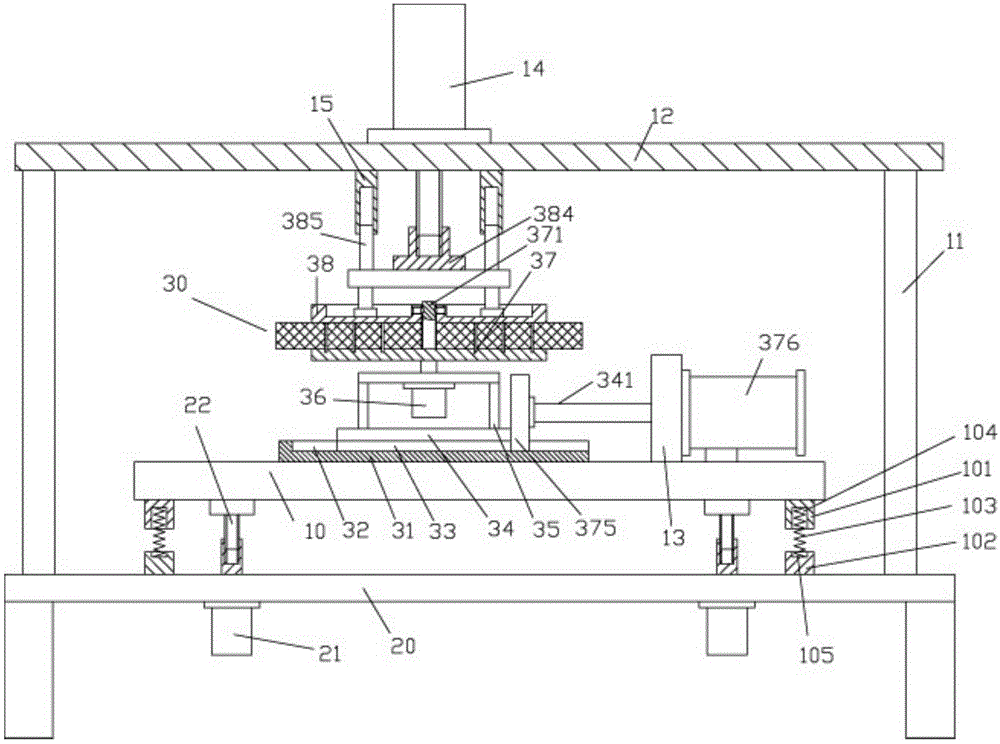
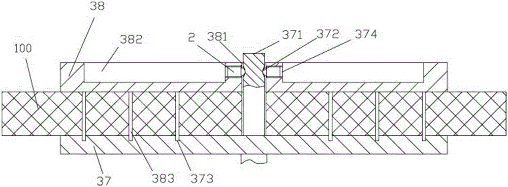
[0016] Example, see as Figure 1 to Figure 2 As shown, an up and down adjustable clamping device for a sponge cutting mechanism includes a frame 20. A plurality of lifting motors 21 are fixed on the top plate of the frame 20, and the output axis of the lifting motor 21 extends upward from the top plate and is screwed. A lifting screw 22 is connected. The lifting screw 22 is fixed on the bottom surface of the bottom lifting plate 10. A sliding rail 31 is fixed on the top surface of the bottom lifting plate 10. A pillar 11 is fixed on the edge of the top plate of the frame 20, and the top of the pillar 11 is fixed. On the upper top plate 12, an upper pressure plate pressing motor 14 is fixed on the upper top plate 12. The output shaft of the upper pressing plate pressing motor 14 penetrates the upper top plate 12 and is screwed on the top of the upper plate 38. A plurality of limit rods 385 are fixed on the top surface of the upper pressure plate 38 on the stud bolt 384, and the ...


PUM


Abstract

The invention discloses an upper lower adjustable clamp apparatus for a sponge cutting mechanism, which comprises a rack, wherein the a plurality of lifting motors are fixed on a top plate of the rack; output shafts of the lifting motors upwardly extends outside the top plate and the output shafts are threadingly connected to lifting threaded rods; the lifting threaded rods are fixed on a bottom surface of a bottom lifting plate; a slide track is fixed on the top surface of the bottom lifting plate; a support column is fixed on an edge portion of the top plate of the rack; the top portion of the support column is fixed on an upper top plate; a lower pressing motor of an upper pressing disc is fixed on the upper top plate; an output shaft of the lower pressing motor of the upper pressing disc downwardly penetrates through the top plate and the output shaft of the lower pressing motor is threadingly connected a thread connecting column set on the top portion of the upper pressing disc; a plurality of stopper rods are fixed on the top surface of the upper pressing disc; and the stopper rods are inserted into a plurality of sleeve cylinders set on the bottom surface of the upper top plate. The apparatus provided herein can be mounted on a position of an electric resistance wire cutting apparatus; a sponge block can be automatically fixed; the sponge block can be lifted and dropped, thus the height is corresponding to the electric resistance wire cutting apparatus; the cutting is convenient; and the effect is good.

Description

Technical field: [0001] The present invention relates to the technical field of sponge cutting, and more specifically to a vertically adjustable clamping device for a sponge cutting mechanism. Background technique: [0002] At present, when making warm earmuffs, the interior needs to be filled with sponge, and the sponge needs to be cut into a small round shape. The existing method is to use manual scissors to cut it down, which is very troublesome and greatly reduces the production efficiency. The circular cut precision is low; [0003] However, the existing sponge is cut into blocks with resistance wire cutting, which has high cutting accuracy, but it does not have a device capable of cutting round shapes. Summary of the invention: [0004] The purpose of the present invention is to overcome the shortcomings of the prior art and provide an up-and-down adjustable clamping device for a sponge cutting mechanism, which can be installed at the resistance wire cutting device, can autom...

Claims


Application Information

Patent Timeline
IPC IPC(8): D06H7/00D06H7/22
Inventor 王胤华尤吉吴春慧周小春傅野吴崧浩
Owner 南通真馨家纺有限公司
Why Eureka
Try Eureka