
Prefabricated concrete component, shear wall module with same and making method of prefabricated concrete component

A prefabricated concrete and shear wall technology, applied to building components, manufacturing tools, walls, etc., can solve the problems of increased workload and production time, inability to pour at the same time, poor bonding integrity of contact surfaces, etc., and achieve reliable quality , making the effect of standardized size and high efficiency

Active Publication Date: 2016-01-06
JINAN RAILWAY TRANSPORT GRP CO LTD
View PDF7 Cites 3 Cited by
  • Summary
  • Abstract
  • Description
  • Claims
  • Application Information

AI Technical Summary

Problems solved by technology

[0005] However, the single prefabricated concrete components of the existing prefabricated concealed support energy-consuming shear walls have many defects, specifically: on the one hand, during factory production, each single precast concrete component cannot be poured at the same time. For the force wall, only the bottom concrete slab steel bars and hidden frame steel bars can be bound first, the bottom concrete slab is poured, and after it reaches a certain strength, the shear wall steel bars are bound, and the hidden frame and shear wall panels are poured. It will increase the workload and production time; on the other hand, because it cannot be poured at the same time, the bonding integrity of the contact surface between the individual precast concrete components is not good

Method used


Image

  • Prefabricated concrete component, shear wall module with same and making method of prefabricated concrete component
  • Prefabricated concrete component, shear wall module with same and making method of prefabricated concrete component
  • Prefabricated concrete component, shear wall module with same and making method of prefabricated concrete component

Examples


Embodiment

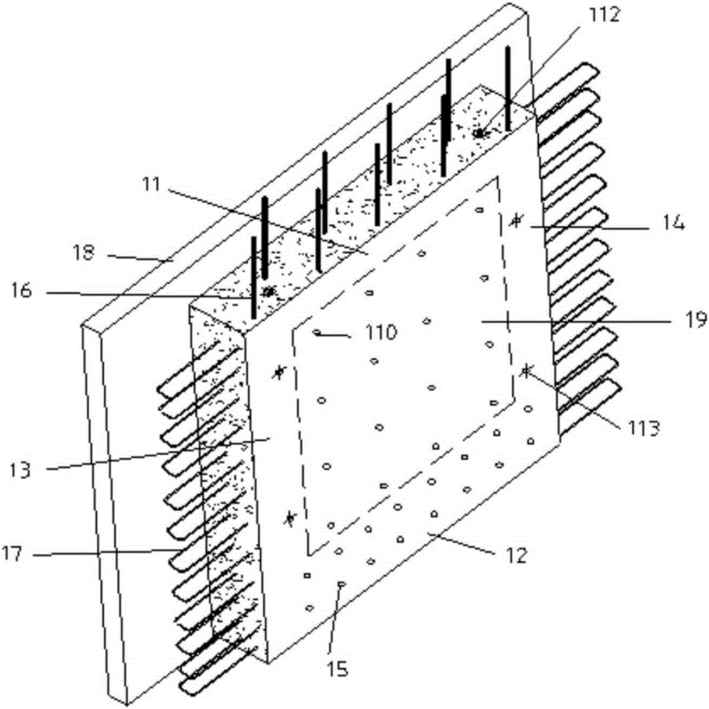
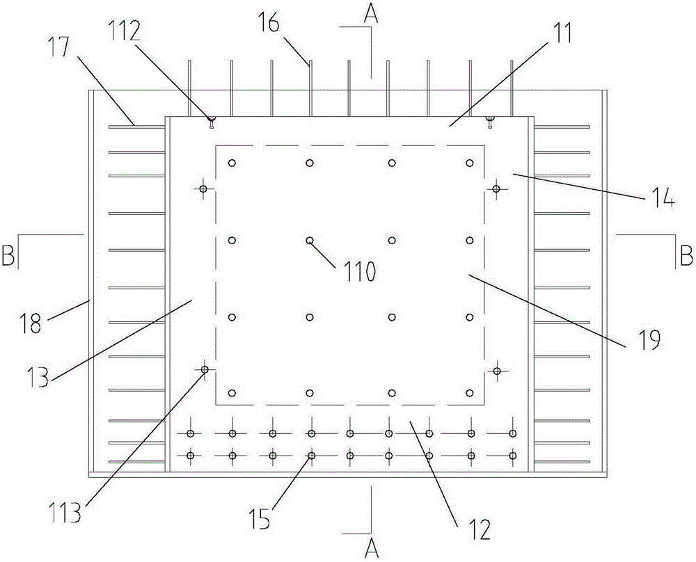
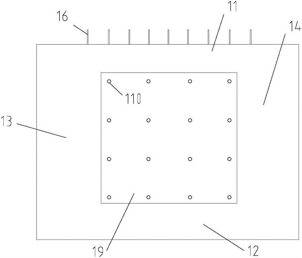
[0049] Embodiment: a kind of prefabricated concrete component, its structure is as Figure 1-7 As shown, including the first shear wall panel 19, the first shear wall panel 19 is provided with reinforcing bars;

[0050] The periphery of the first shear wall panel 19 is fixedly connected with the edge dark frame. The edge dark frame includes an upper edge dark frame beam 11, a lower edge dark frame beam 12, a left edge dark frame column 13 and a right edge dark frame column 14;

[0051] The backs of the upper edge dark frame beam 11, the lower edge dark frame beam 12, the left edge dark frame column 13 and the right edge dark frame column 14 all have a reinforced concrete slab 18 protruding from the first shear wall panel 19;

[0052] The upper edge concealed frame beam 11, the lower edge concealed frame beam 12, the left edge concealed frame column 13, the right edge concealed frame column 14, the reinforced concrete slab 18 and the first shear wall panel 19 are integrally ca...


PUM


Abstract

The invention relates to a prefabricated concrete component, a shear wall module with the same and a making method of the shear wall module. The prefabricated concrete component comprises a first shear wall plate, rebars are arranged in the first shear wall plate, four sides of the first shear wall plate are integrally formed with an upper edge concealed frame beam, a lower edge concealed frame beam, a left edge concealed frame column and a right edge concealed frame column, a reinforced concrete plate protruding out of the first shear wall plate is arranged on the back of each of the upper edge concealed frame beam, the lower edge concealed frame beam, the left edge concealed frame column and the right edge concealed frame column, a grouting sleeve is embedded in the lower edge concealed frame beam, vertical rebars extending out of the upper edge concealed frame beam are embedded in the upper edge concealed frame beam, each of the left edge concealed frame column and the right edge concealed frame column is provided with a U-shaped closed rebar extending out of the same. The prefabricated concrete component serves as a part of the shear wall module, and the shear wall module can be made by only mounting a concealed support and firmly connecting with another shear wall plate. A concealed support truss is arranged between two shear wall plates, so that good anti-seismic performance is realized.

Description

technical field [0001] The invention relates to the technical field related to construction engineering, in particular to a prefabricated concrete component, a shear wall module with the component and a manufacturing method thereof. Background technique [0002] The shear wall structure has good anti-seismic performance, and has gradually become the structural form commonly used in residential construction in my country. [0003] Ordinary cast-in-place reinforced concrete shear walls mainly resist horizontal earthquake force through horizontal steel bars, but under earthquakes, ordinary cast-in-place shear walls are prone to brittle shear failure, and their ductility and energy dissipation capacity are insufficient. The existing prefabricated integral shear wall is just a simple split of the cast-in-place shear wall, which is difficult to meet the ductility and energy dissipation and anti-seismic requirements. [0004] The prefabricated concealed support energy-dissipating ...

Claims


Application Information

Patent Timeline
IPC IPC(8): E04B2/00E04B2/64E04C2/28E04C2/38B28B23/02
Inventor 王国富张中勇
Owner JINAN RAILWAY TRANSPORT GRP CO LTD
Learn More