Mitigative transition non-linear rigid traction joint and non-linear rigidity control method thereof
A nonlinear and rigid technology, applied in springs, springs/shock absorbers, mechanical equipment, etc. made of plastic materials, can solve the problem of insufficient nonlinear stiffness to ease transition characteristics, and achieve the effect of optimal riding comfort
- Summary
- Abstract
- Description
- Claims
- Application Information
AI Technical Summary
Problems solved by technology
Method used
Image
Examples
Embodiment 1
[0033] Embodiment 1: as Figure 3 to Figure 7As shown, a traction node with moderate transitional nonlinear stiffness includes a metal mandrel, a metal sheath 5 and a rubber elastic body 6, the metal mandrel includes a shaft body 41 and a flange 42 arranged in the middle of the shaft body 41, The rubber elastic body 6 is arranged between the metal mandrel flange 42 and the metal jacket 5, and the traction node forms a real direction X and a space direction Y along its radial direction (the space direction Y is the working direction), and The real direction X and the empty direction Y are perpendicular to each other; along the real direction X, the metal mandrel flange 42, the rubber elastic body 6 and the metal jacket 5 are bonded to form a real structure, and along the empty direction Y, the rubber elastic body 6 is provided with a space 61 symmetrical to the axis of the metal mandrel 7, and the metal mandrel flange 42 is a prism whose bottom surface 45 is a parallelogram, an...
Embodiment 2
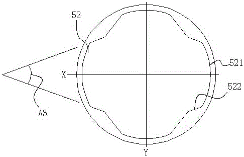
[0043] Embodiment 2: as Figure 9 and Figure 10 As shown, compared with Example 1, the difference is that: along the real direction X, on the inner wall of the metal jacket 5, a real direction groove 52 symmetrical to the axis of the metal mandrel is provided, and the rubber elastic body The outer surface and the inner surface of 6 match with the inner wall surface of the metal jacket 5 and the outer surface of the metal mandrel flange 42 respectively.
[0044] When the traction joint is vulcanized and formed, the metal mandrel, the metal jacket and the elastic rubber body are formed into a whole through vulcanization, and the vulcanized body is subjected to radial extrusion and then secondary finishing to form a finished product. After the radial extrusion, since the rubber of the elastic rubber body along the empty direction Y is less than that along the real direction X and has gaps, the reaction force of the rubber elastic body due to radial extrusion is in the air direc...
Embodiment 3
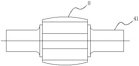
[0047] Embodiment 3: as Figure 11 to Figure 13 As shown, compared with Example 1, the difference is that a pair of opposite rounded corners of the parallelogram prism in the air direction Y are provided with a radian 8 in the axial direction of the metal core axis, and the opposite The arc of the rounded corners is symmetrical about the axis of the metal mandrel, that is, a pair of opposite rounded corners of the flange of the metal mandrel in the air direction Y are arc-shaped in the axial direction of the metal mandrel, and the opposite arc-shaped circles The angular parts are symmetrical about the axis of the metal mandrel.
[0048] In order to reduce the deflection stiffness when the traction node is working, in this embodiment, a pair of opposite rounded corners of the parallelogram prism in the space direction X are designed as rounded corners 9 with radians along the axial direction of the metal mandrel. This radian makes the free surface of the rubber body greatly in...
PUM
 Abstract
Description
Claims
Application Information
 - R&D
- Intellectual Property
- Life Sciences
- Materials
- Tech Scout
- Unparalleled Data Quality
- Higher Quality Content
- 60% Fewer Hallucinations
Browse by: Latest US Patents, China's latest patents, Technical Efficacy Thesaurus, Application Domain, Technology Topic, Popular Technical Reports.
© 2025 PatSnap. All rights reserved.Legal|Privacy policy|Modern Slavery Act Transparency Statement|Sitemap|About US| Contact US: help@patsnap.com


