

City regional railway signal system and control method thereof
A railway signal and control method technology, applied in automatic systems and other directions, can solve the problems of many trackside equipment, heavy maintenance workload, and large investment in system construction, so as to save investment costs, reduce labor intensity, and improve the degree of automatic control. Effect
- Summary
- Abstract
- Description
- Claims
- Application Information
AI Technical Summary
Problems solved by technology
Method used
Image

Examples
Embodiment Construction
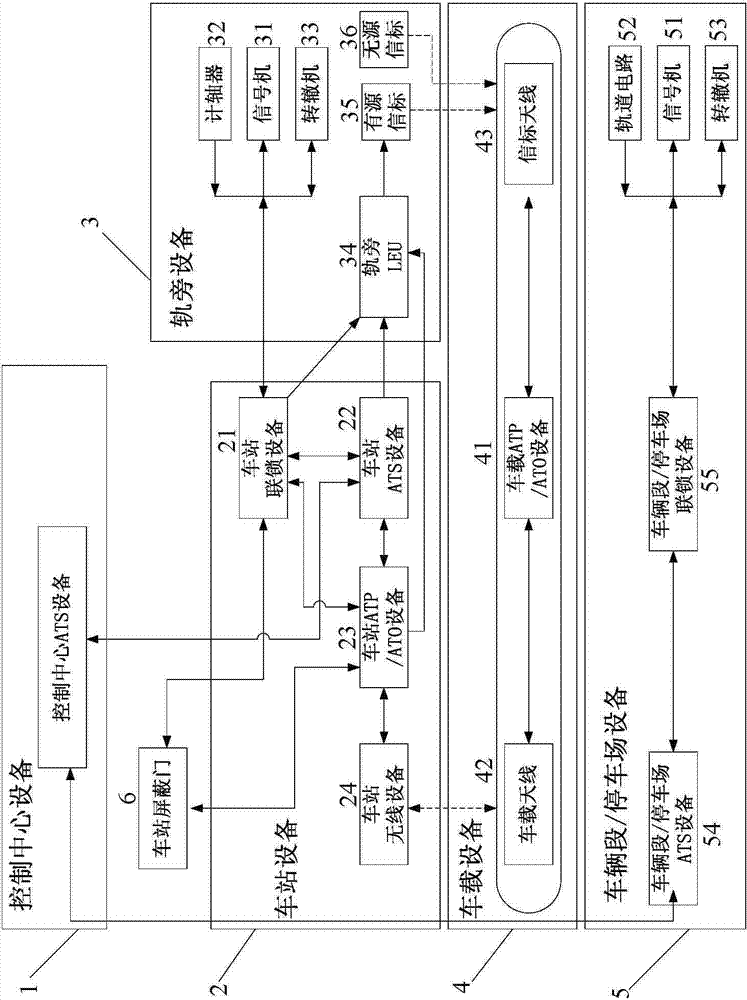
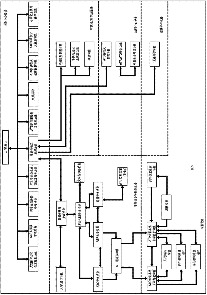
[0062] The main functions of the urban railway signal system of the present invention include the functions of the Automatic Train Supervise (ATS) subsystem, the Automatic Train Protection (ATP) subsystem, the ATO subsystem, the main line interlocking subsystem, and the depot / Parking lot interlocking subsystem, training subsystem, power supply subsystem, centralized monitoring subsystem and data communication subsystem.
[0063] Among them: the main function of the ATS subsystem is to compile and manage the train operation plan, to realize the automatic monitoring of the whole line of trains and the automatic management of train operation. Specifically, control of train route, display of driving information, description of train operation, collection and acquisition of information, management of train diagram / schedule, train operation plan and vehicle management, adjustment of train operation, query of train operation, platform departure Instruction display, operation record ...
PUM
 Abstract
Description
Claims
Application Information