Method and apparatus for unified simulation

Inactive Publication Date: 2006-01-31
ARM LTD
View PDF12 Cites 63 Cited by
  • Summary
  • Abstract
  • Description
  • Claims
  • Application Information

AI Technical Summary

Benefits of technology

[0019]The present invention provides a significant improvement over the conventional method of simulating the hardware and software components of SOC system designs. The present invention successfully integrates the hardware and software components of a system design in a single unified simulation environment. Additionally, the unified simulation environment has the advantage of running as a single process, which significantly improves debugging capabilities. Furthermore, the present invention employs a higher level of abstraction than conventional HDL system models, which significantly reduces simulation times while moving away from the detail saturated event driven simulations of the past.
[0020]The unified simulation environment focuses on integrating simulations of the hardware and software components of an embedded system design. For example, in a unified hardware-software simulation environment, the virtual prototype of the digital system design includes a high level general purpose programming language model of the system's memory components. Additionally, the unified simu

Problems solved by technology

In today's world of system-on-a-chip (“SOC”) designs, the emulation method is becoming increasingly untenable.
Another drawback of using test boards is the lead time required to build a physical test board and the lead time required to create the necessary interfaces between the components of the system.
This additional delay, which typically can be as much several months per test board, so significantly increases the time for each iterative refinement step in the design cycle that emulation is nearly too burdensome to be useful in today's competitive reduced time-to-market environment.
The use of these standard memory chips and their attendant interfaces further deviates the physical test board model from the actual design.
For at least these reasons, the use of physical test boards to emulate electronic system designs is not very desirable.
For example, it may only require a few days to create an HDL system model while creation of a physical test board typically may require several months.
Also, it may only require a few hours to create an iterative second version HDL system model versus the several months required to create a similar second version test board.
However, although a system model has definite advantages over a physical test board, it has several drawbacks.
With the growing complexity of systems comprising a mix of micro controllers, digital signal processors (“DSP”), random access memory (

Method used


Image

  • Method and apparatus for unified simulation
  • Method and apparatus for unified simulation
  • Method and apparatus for unified simulation

Examples


Embodiment Construction

[0038]The present invention is directed toward a method for simulating hardware and software components of a digital system design in a unified simulation environment. After reading this description it will become apparent to one of ordinary skill in the art how to implement the invention in alternative embodiments and alternative applications. As such, this detailed description of various alternative embodiments should not be construed to limit the scope or breadth of the present invention.

I. Introduction

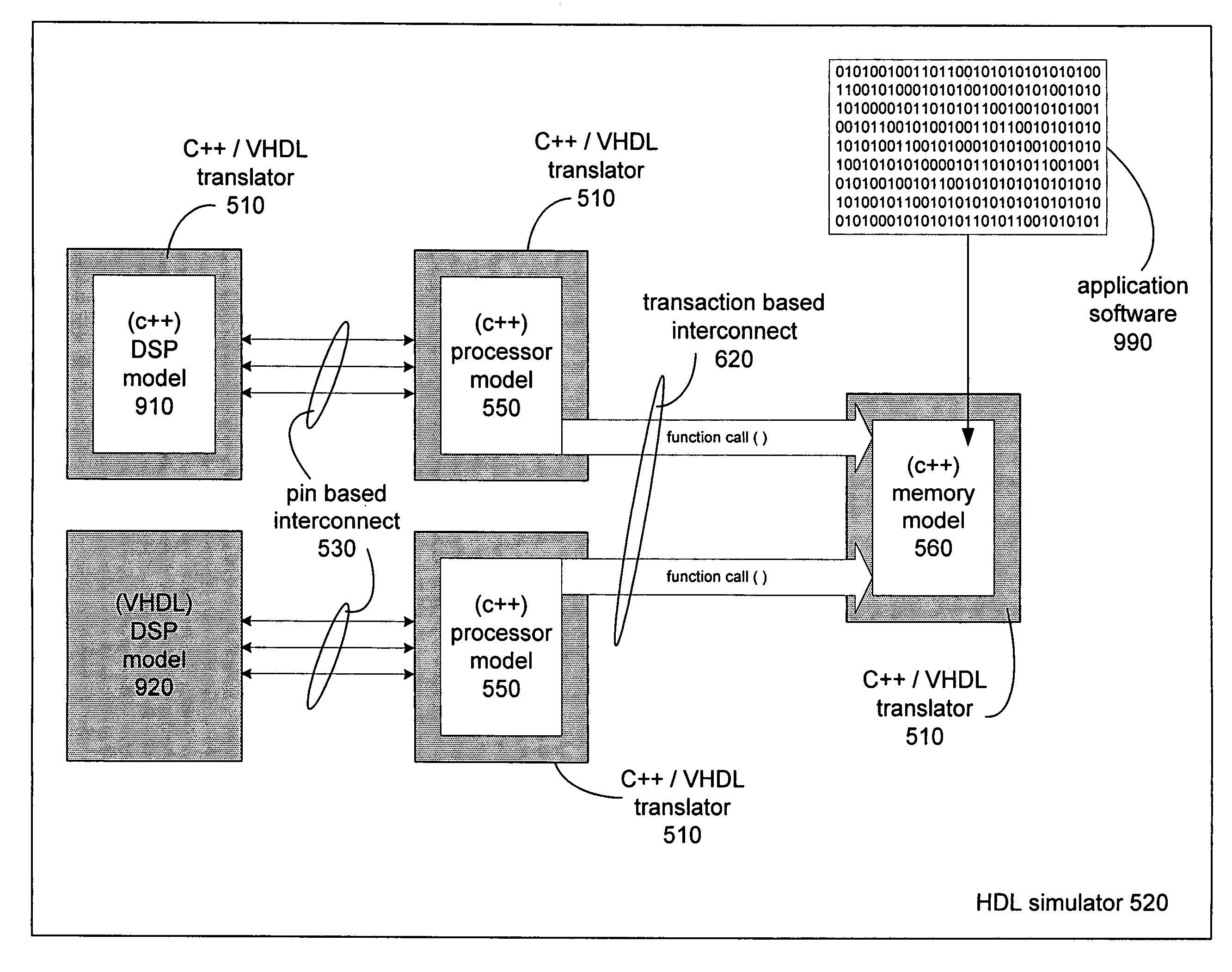
[0039]The increasing complexity of the current generation of system designs requires high speed system validation models. A system validation model may be a physical prototype, such as a system emulation board. A system validation model may also be a system simulation model created with the aid of computer software. A system simulation model that mimics the design of a particular system is known as a virtual prototype. A virtual prototype can model, for example, an SOC system with ...


PUM


Abstract

A significant improvement over current methods for co-simulation of the hardware and software components of embedded digital system designs is provided. The present invention integrates the hardware and software components of a system design into a single unified simulation environment. The unified simulation environment and the various component models of the system design are created in a high level general purpose programming language. This allows inter-component communications and communications with the unified simulation environment to be carried out through the use of function calls, which significantly increases the overall simulation speed. Additionally, the unified simulation environment runs as a single process, which significantly improves debugging capabilities. Furthermore, the present invention employs a higher level of abstraction than conventional simulation environments and thereby significantly increases simulation speed while moving away from the detail saturated event driven simulations of the past.

Description

RELATED APPLICATION[0001]The present application relates to co-pending United States patent application of concurrent ownership entitled “METHOD AND APPARATUS FOR ACCELERATING HARDWARE SIMULATION,” Ser. No. 09 / 586,325, filed on Jun. 2, 2000 and which is hereby incorporated by reference in its entirety.BACKGROUND OF THE INVENTION[0002]1. Field of the Invention[0003]The present invention relates generally to the field of digital design system verification and more specifically relates to advanced simulation techniques for digital system designs.[0004]2. Related Art[0005]In the electronic design automation (“EDA”) market today, the general design cycle for digital systems involves creating a design for the system, validating the design, and then manufacturing the system. The validation process is the focus of the present invention.[0006]Currently, system designs are validated using one of two methodologies. The first method involves creating a physical hardware replica of the design on...

Claims


Application Information

Patent Timeline
IPC IPC(8): G06F17/50
CPCG06F17/5022G06F2217/86G06F2117/08G06F30/33
Inventor BORTFELD, ULRICH
Owner ARM LTD
Why Eureka
Try Eureka