Efficient boiled off gas (BOG) after-condenser

A flash gas and condenser technology, applied in the field of high-efficiency flash gas (BOG) recondensers, can solve the problems of low condensation efficiency, complex equipment, and difficult control, and achieve sufficient condensation, simplified operation, and reduced flow dead ends. Effect

Active Publication Date: 2016-01-06
江苏中圣压力容器装备制造有限公司
View PDF9 Cites 7 Cited by
  • Summary
  • Abstract
  • Description
  • Claims
  • Application Information

AI Technical Summary

Problems solved by technology

[0005] The purpose of the present invention is to design a low energy consumption and compact structure for the existing BOG recondensation technology, which has low condensation efficiency, complex equipment, difficult control, and the process is affected by the flow and pressure of upstream and downstream LNG. Recondenser capable of fully condensing BOG

Method used


Image

  • Efficient boiled off gas (BOG) after-condenser
  • Efficient boiled off gas (BOG) after-condenser
  • Efficient boiled off gas (BOG) after-condenser

Examples


Embodiment 1

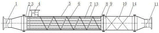
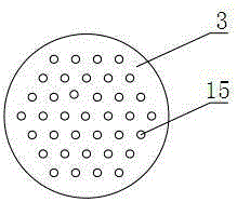
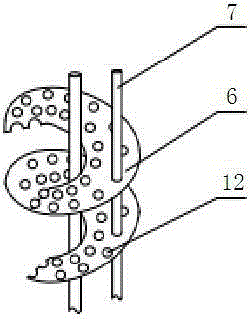
[0024] Such as Figure 1 to Figure 4 As shown, a high-efficiency flash gas (BOG) recondenser includes a first shell 5, a second shell 14, an LNG inlet 4 located on the first shell 5, and a The tube plate 3 and the supporting grid 8 at both ends of the housing 5 are connected to the BOG inlet 1. A plurality of microporous tubes 7, a distance rod 13 and a spiral are arranged between the tube plate 3 and the supporting grid 8. The deflector 6, the spiral deflector 6 is provided with a tube hole 12, the tube plate 3 is provided with a tube sheet tube hole 15, the surface of the microporous tube 7 is provided with micropores, the microporous tube 7 and the fixed The distance rod 13 passes through the tube hole 12 on the spiral baffle 6 and is fixed in parallel between the tube plate 3 and the supporting grid 8; one end of the second shell 14 is connected to the first shell 5 through a connecting flange 9. The other end is connected to the LNG outlet 11, and a static mixing unit 10 ...

Embodiment 2

[0027] Such as Image 6 As shown, on the basis of Example 1, the micropore diameter of the microporous tube 7 is 10 μm, and the arrangement angle between the microporous tubes is 30 degrees. One end of the microporous tube 7 is connected to the tube on the tube plate 3. The plate tube hole 15 is butted, the other end is movably overlapped with the supporting grid, and the end on the side of the supporting grid is blocked; the microporous tube and the tube plate are connected by thread.

Embodiment 3

[0029] On the basis of Example 1, the micropore diameter of the microporous tube 7 is 60 μm, and the arrangement angle between the microporous tubes is 45 degrees. One end of the microporous tube 7 is connected to the tube plate tube hole on the tube plate 3. 15 butt joint, the other end is movably overlapped with the supporting grid, and the end on the side of the supporting grid is blocked; the microporous tube and the tube sheet are connected by thread.


PUM


Abstract

The invention discloses an efficient boiled off gas (BOG) after-condenser. The efficient BOG after-condenser comprises a first shell, a second shell, a liquefied natural gas (LNG) inlet formed in the first shell, a pipe plate and a supporting grid, wherein the pipe plate and the supporting grid are located at the two ends of the first shell respectively; the pipe plate is connected with a BOG inlet; a plurality of micro pore pipes, fixed-interval rods and spiral flow guide plates are arranged between the pipe plate and the supporting grid; the spiral flow guide plates are provided with pipe pores; the pipe plate is provided with pipe plate pipe pores; the surfaces of the micro pore pipes are provided with micro pores; the micro pore pipes and the fixed-interval rods penetrate through the pipe holes in the spiral flow guide plates and are fixed between the pipe plate and the supporting grid in parallel; one end of the second shell is connected with the first shell through a connecting flange, and the other end of the second shell is connected with an LNG outlet; a static mixing unit is arranged inside the second shell. Compared with traditional BOG after-condensation equipment, the efficient BOG after-condenser is high in condensation efficiency, high in processing capacity, easy to operate and convenient to maintain and replace.

Description

Technical field [0001] The invention relates to a condenser, in particular to a high-efficiency flash steam (BOG) recondenser. Background technique [0002] According to the different treatment methods for the flash vapor (BOG) of liquefied natural gas (LNG) storage tanks, there are two types: direct output method and recondensation method. The direct output method is to compress the flash vapor (BOG) to the external transmission pressure and send it directly to the gas transmission network; the recondensation method is to compress the flash vapor (BOG) to a lower pressure (usually 0.7MPa), and The LNG delivered from the LNG storage tank by the LNG low-pressure transfer pump is mixed in the condenser. Since the LNG is in a supercooled state after being pressurized, the flash vapor can be recondensed. After the condensed LNG is pressurized by the LNG high-pressure transfer pump, it is then vaporized and transported. The recondensation method can utilize the cold capacity of LNG,...

Claims


Application Information

Patent Timeline
Patent Type & Authority Applications(China)
IPC IPC(8): F28B3/00
Inventor 郭宏新刘世平刘丰高辉周宁波李奇
Owner 江苏中圣压力容器装备制造有限公司
Why Eureka
Try Eureka