A sensor installation adjustment device

An installation adjustment, sensor technology, applied in the direction of measuring devices, instruments, etc., to achieve the effect of precise horizontal adjustment, improved installation accuracy, and efficient horizontal installation

CN105222734BActive Publication Date: 2018-04-06HENAN UNIV OF SCI & TECH
6 Cites 0 Cited by

Patent Information

Authority / Receiving Office
CN · China
Patent Type
Patents(China)
Current Assignee / Owner
Publication Date
2018-04-06

Smart Images

  • Figure 1
    Figure 1
  • Figure 2
    Figure 2
  • Figure 3
    Figure 3
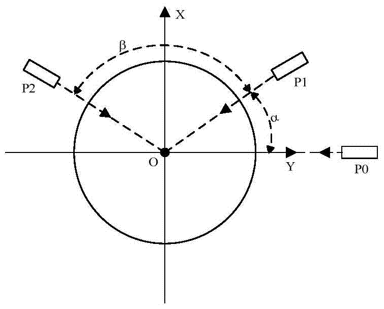
Patent Text Reader

Abstract

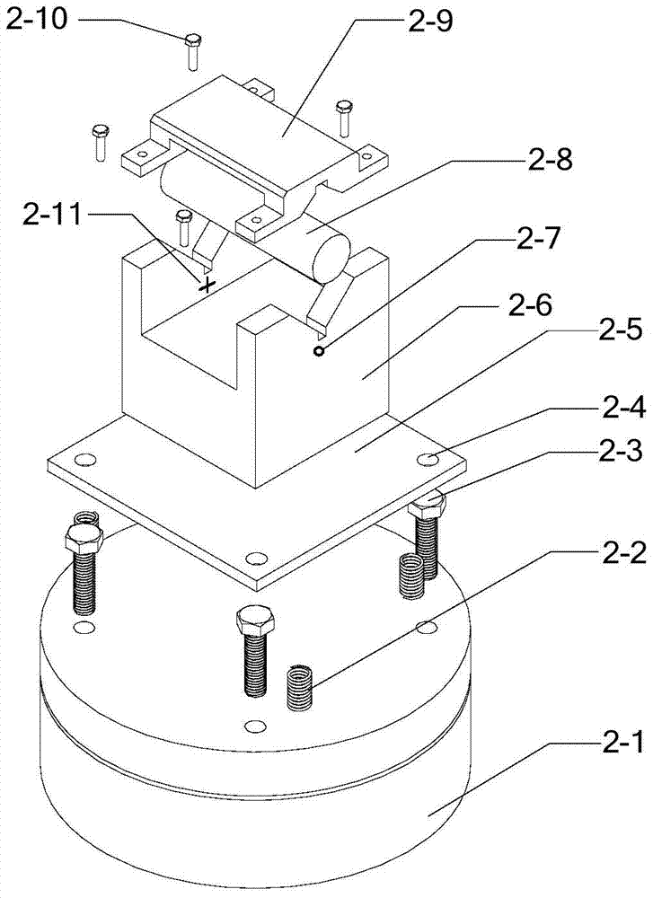
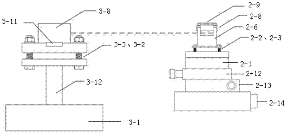
The invention relates to a sensor mounting adjustment device, which comprises a base, and a sensor fixing seat arranged above the base, wherein at least three height adjustment parts arranged at intervals around the circumferential direction for adjusting level of the sensor fixing seat are arranged between the base and the sensor fixing seat; the sensor fixing seat is provided with a sensor fixing structure for fixing the sensor; and the sensor fixing seat is provided with a level alignment mechanism matched with a leveling reference device at the central position for displaying the level state of the sensor. The device can realize level sensor adjustment flexibly, high efficiently and accurately, the sensor position mounting precision is improved, and the roundness error measurement precision and the rotation error measurement precision can be ensured.
Need to check novelty before this filing date? Find Prior Art

Description

technical field

[0001] The invention belongs to the technical field of rotary error separation of rotary shafts, and in particular relates to a sensor installation and adjustment device. Background technique

[0002] Roundness error is one of the important indicators to measure the shape accuracy of cylindrical parts. The size of the roundness error of parts seriously affects the working performance and motion performance of parts, and affects the overall performance of mechanical equipment. When measuring the roundness error of parts and the rotation accuracy of the rotary axis of the machine tool on site, error separation technologies such as the three-point method in the time domain and the three-point method in the frequency domain are often used to realize the separation of the axis rotation error and the roundness error of the part. Eccentric characteristics, and has a high test accuracy. Since the three-point roundness error separation technology requires the install...

Examples

Embodiment Construction

[0018] The technical solution of the present invention will be described in detail below in conjunction with the accompanying drawings.

[0019] The principle of three-point method error separation technology is as follows: figure 1 shown. The three sensors P0, P1, and P2 are installed at different positions on the circumference of the workpiece, and the angles between the three sensors are α and β respectively. It is required that the installation axes of the three sensors intersect at the center of the circle O, which is also the origin and origin of the coordinate system XOY. Rotate the center of the table. When measuring, the sensor is fixed, and the workpiece to be measured is driven by the rotary table to make a rotary motion. According to the output equation of the measurement results and the error separation equation of the three-point method, the roundness error of the workpiece and the rotation error of the rotary axis can be separated by using appropriate paramete...